

REMOVING/INSTALLING THE STATOR ASSEMBLY
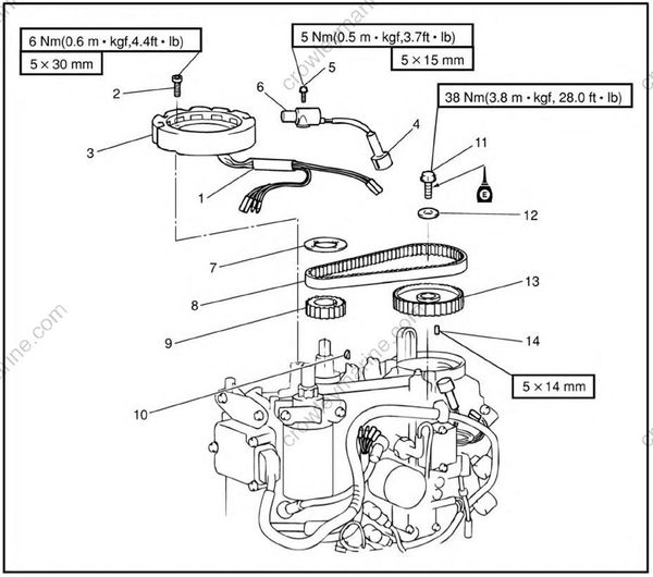
| Order | Job/Part | Q'ty | Remarks |
|---|---|---|---|
| 1 | Stator connector | 1 | |
| 2 | Bolt | 3 | |
| 3 | Stator | 1 | |
| 4 | Pulser coil coupler | 1 | |
| 5 | Bolt | 2 | |
| 6 | Pulser coil | 1 | |
| 7 | Plate | 1 | |
| 8 | Timing belt | 1 | |
| 9 | Drive sprocket | 1 | |
| 10 | Woodruff key | 1 | |
| 11 | Bolt | 1 | |
| 12 | Washer | 1 | |
| 13 | Driven sprocket | 1 | |
| Continued on next page. |
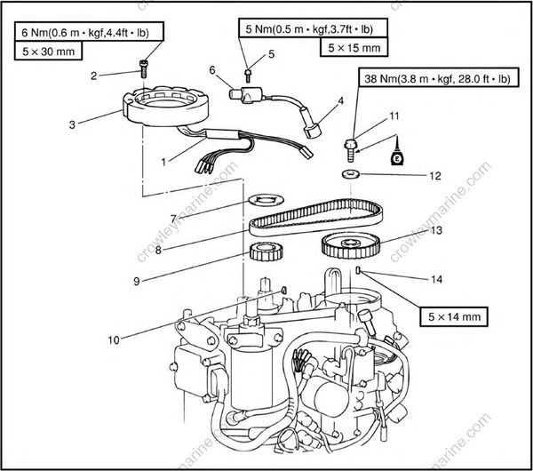
| Order | Job/Part | Q'ty | Remarks |
|---|---|---|---|
| 14 | Dowel pin | 1 | |
| For installation, reverse the removal procedure. |
REMOVING THE SPROCKETS
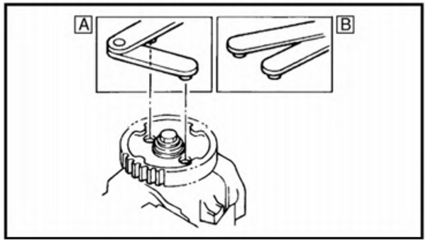
CAUTION:
Make sure cylinder # 1's position is at TDC before removal.
Remove:
Bolt
Washer
Driven Sprocket
Dowel pin
Flywheel magnet assembly holder: YB-06139/90890-06522
[A] For USA and Canada
[B] Except for USA and Canada
INSTALLING THE TIMING BELT AND SPROCKETS
- Install:
Drive sprocket
Driven sprocket
Driven sprocket bolt: 38 Nm (3.8 m-kgf, 28 ft-lb)
Flywheel magnet assembly holder: YB-06139/90890-06522
- Install
- Timing belt
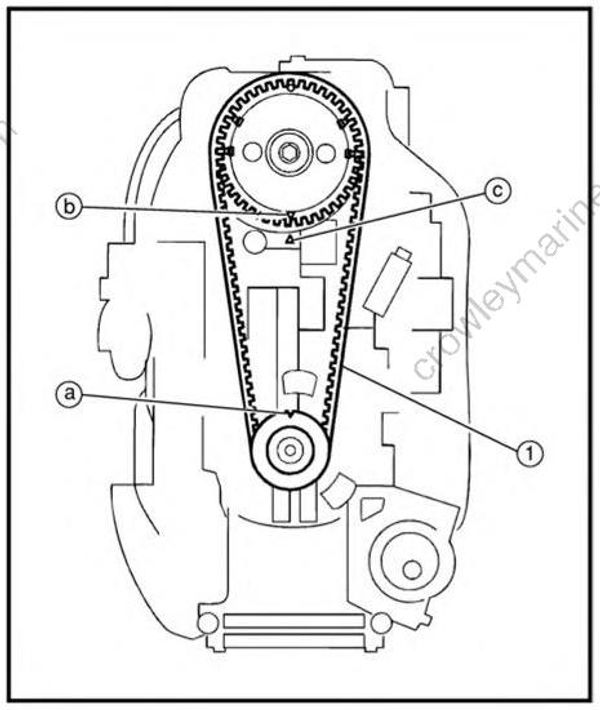
Installing steps
(1) Align mark hole (a) of the drive sprocket with engine centerline.
(2) Align mark (b) on the driven sprocket with a (c) on the cylinder head.
(3) Install the timing belt (1).
(4) Turn the crankshaft clockwise two times and make sure the drive sprocket and driven sprocket are correctly aligned with the marks.