

EXPLODED DIAGRAM
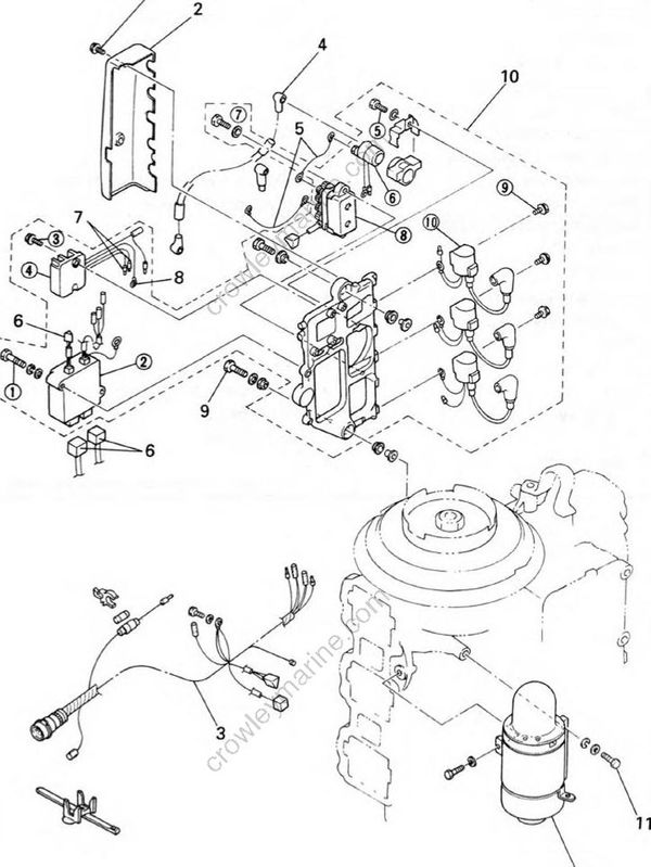
REMOVAL AND INSTALLATION CHART
| Step | Procedure/Part name | Q'ty | Service points |
|---|---|---|---|
| ELECTRICAL UNIT REMOVAL | Follow the left "Step" for removal | ||
| 1 | Screw | 2 | |
| 2 | Cover | 1 | |
| 3 | Wire harness | 1 | |
| 4 | Battery cable | 1 | |
| 5 | Wire lead | 2 | |
| 6 | CDI unit coupler | 3 | |
| 7 | Lighting coil lead | 2 | |
| 8 | Rectifier regulator earth lead | 4 | |
| 9 | Bolt (with washer) | 2 | |
| 10 | Electrical unit assembly | 1 | |
| 11 | Bolt (with washer) | 3 | |
| 12 | Starter motor | 1 | |
| ELECTRICAL UNIT DISASSEMBLY | |||
| (1) | ELECTRICAL UN | 2 | |
| (2) | CDI unit | 1 | |
| (3) | Bolt (with washer) | 2 | |
| (4) | Rectifier regulator | 1 | |
| (5) | Bolt | 1 | |
| (6) | Starter relay | 1 | |
| (7) | Bolt |
2 | |
| (8) | PTT relay | 1 | |
| (9) | Bolt | 3 | |
| (10) | Ignition coil | 3 | |
| Reverse the removal steps for installation. |