

Cylinder head
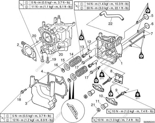
| No | Part name | Q'ty | Remarks |
|---|---|---|---|
| 1 | Cylinder head | 1 | |
| 2 | Gasket | 1 | Not reusable |
| 3 | Cylinder head cover | 1 | |
| 4 | Gasket | 1 | Not reusable |
| 5 | Intake valve | 1 | |
| 6 | Exhaust valve | 1 | |
| 7 | Push rod | 2 | |
| 8 | Push rod guide | 1 | |
| 9 | Stud bolt | 2 | |
| 10 | Rocker arm | 2 | |
| 11 | Rocker arm pivot | 2 | Not reusable |
| 12 | Valve guide | 2 | Not reusable |
| 13 | Stem seal | 2 | |
| 14 | Valve spring | 2 | |
| 15 | Valve spring retainer | 2 | |
| 16 | Valve cotter | 2 | |
| 17 | Bolt | 4 | M8 x 60 mm |
| 18 | Bolt | 6 | M6 x 16 mm |
| 19 | Bolt | 2 | M6 x 45 mm |
| 20 | Dowel | 2 | |
| 21 | Nut | 2 | |
| 22 | Blowby hose | 1 |
Removing the cylinder head
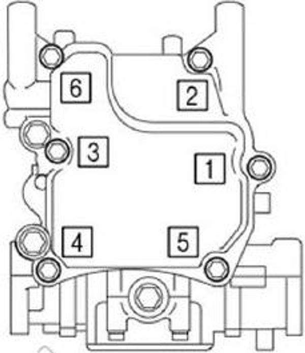
- Remove the cylinder head cover bolts in the sequence shown.
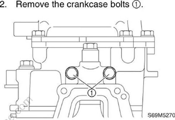
- Remove the crankcase bolts (1)
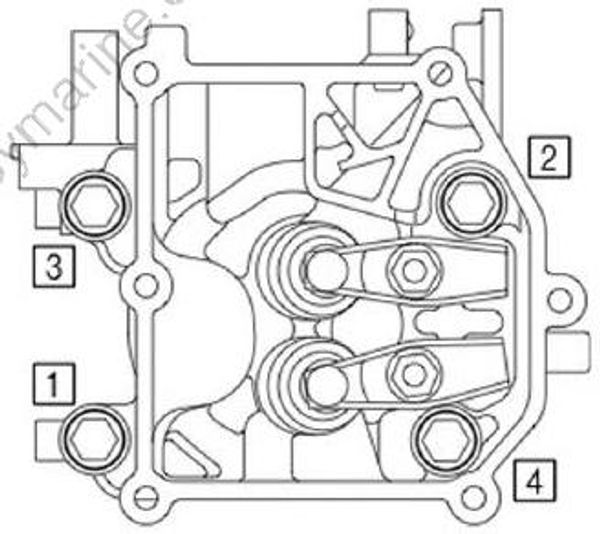
- Remove the cylinder head bolts in the sequence shown.
CAUTION:
Do not scratch or damage the mating surfaces of the cylinder head and cylinder block.
- Remove the cylinder head, and then remove the push rods.
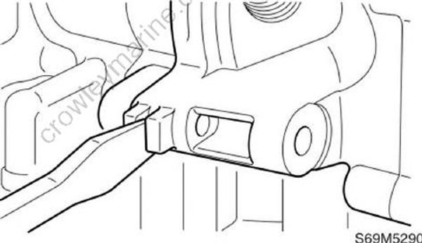
NOTE:
Insert a flat head screwdriver between the tab of the cylinder and the tab of the cylinder head to pry open the two parts.
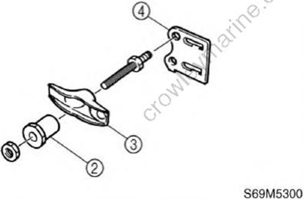
- Remove the rocker arm pivot (2) rocker arm (3) and push rod guide (4).
- Remove the intake valve and exhaust valve.
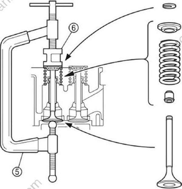
NOTE:
Be sure to keep the valves, springs, and other parts in the order as they were removed.
Valve spring compressor (5): YM-01253
Valve spring compressor attachment (6): YB-06320
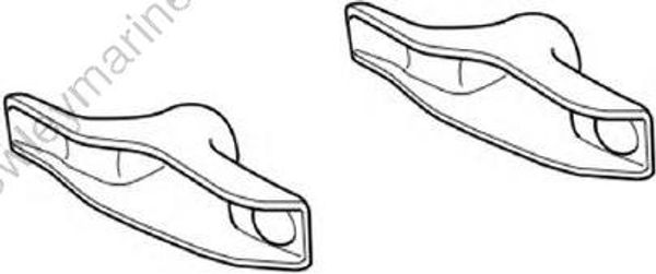
Checking the rocker arms
- Check the rocker arms for cracks, wear,or damage. Replace if necessary.
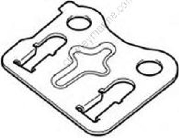
Checking the push rod guide
- Check the push rod guide for cracks or damage. Replace if necessary.
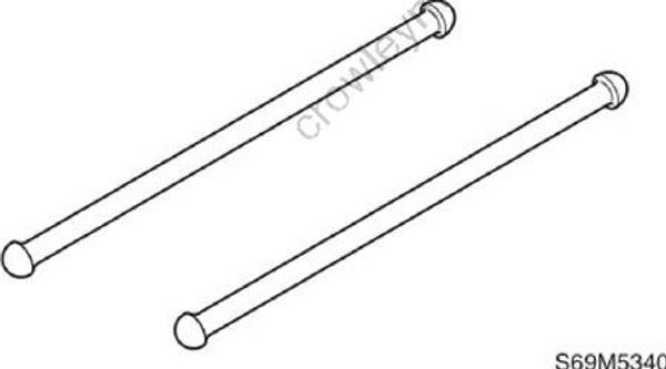
Checking the push rods
- Check the push rods for bends, wear, or damage. Replace if necessary.
Checking the valve springs
- Measure the valve spring free length (a). Replace if out of specification.
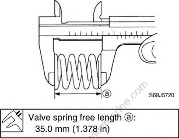
Valve spring free length (a): 35.00mm (1.378 in)
- Measure the valve spring tilt (b). Replace if out of specification.
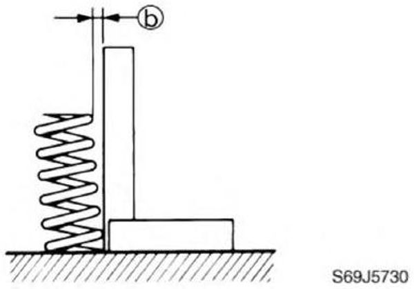
Valve spring tilt limit (b): 1.2 mm (0.05 in)
Checking the valves
Check the valve face for pitting or wear. Replace if necessary.
Measure the valve margin thickness (a). Replace if out of specification.
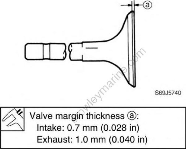
Valve margin thickness (a):
Inatke: 0.7 mm (0.028 in)
Exhaust: 1.0 mm (0.040 in)
- Measure the valve stem diameter (b).Replace if out of specification.
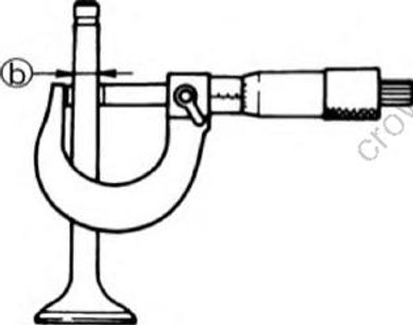
Valve stem diameter (b):
Intake: 5.475-5.490 mm (0.2156-0.2161 in)
Exhaust: 5.460-5.475 mm (0.2150-0.2156 in)
- Measure the valve stem runout. Replace if out of specification.
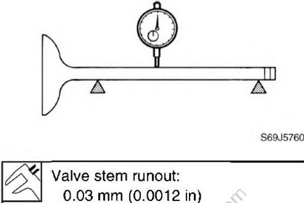
Valve stem runout: 0.03 mm (0.0012 in)
Checking the valve guides
NOTE:
Before checking the valve guide make sure that the valve stem diameter is within specification.
- Measure the valve guide inside diameter (a).
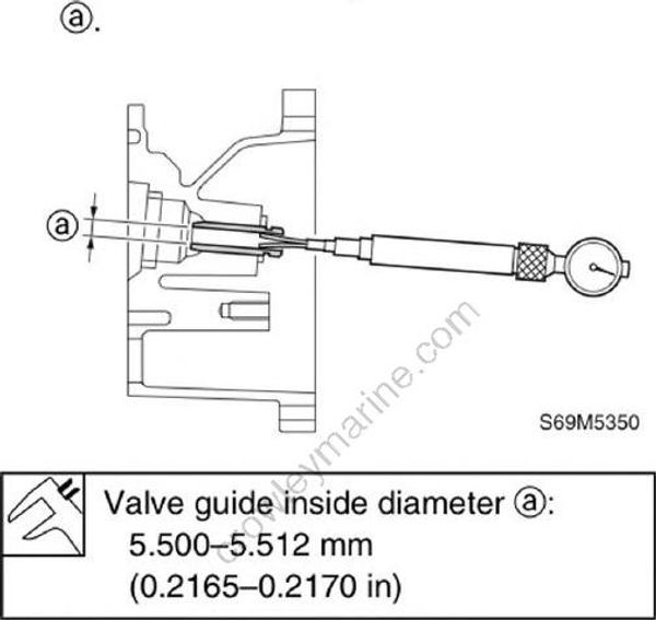
Valve guide inside diameter (a): 5.500-5.512 mm (0.2165-0.2170 in)
- Calculate the valve stem-to-valve guide clearance as follows. Replace the valve guide if out of specification.
Valve stem-to-valve guide clearance = valve guide inside diameter - valve stem diameter:
Intake: 0.010-0.037 mm (0.0004-0.0015 in)
Exhaust: 0.025-0.052 mm (0.0010-0.0020 in)
Replacing the valve guides
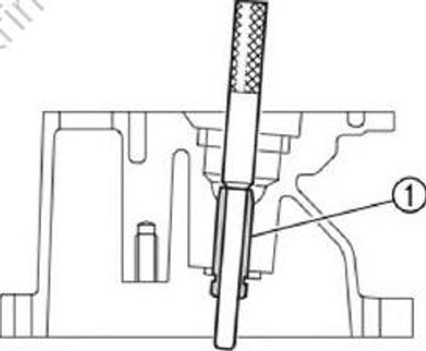
- Remove the valve guide (1) by striking the special service tool from the combustion chamber side.
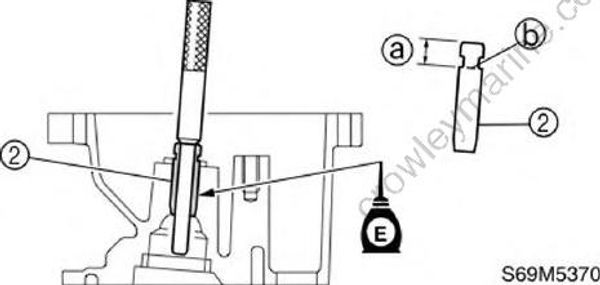
- Install the new valve guide (2) by striking the special service tool from the rocker arm side until the valve guide reaches the specified installation position (a).
Valve guide remover/installer: YB-06801
NOTE:
- Before installing the valve guide, mark its installation position (b) as shown.
- Apply engine oil to the new valve guide.
Valve guide installation position (a): 5.9 mm (0.23 in)
Valve guide remover/installer: YB-06801
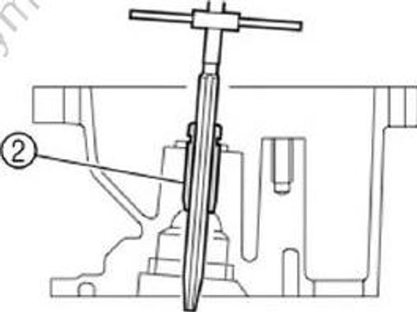
- Insert the special service tool into the valve guide and then ream the valve guide (2)and then ream the valve guide.
NOTE:
- Turn the valve guide reamer clockwise to ream the valve guide.
- Do not turn the reamer counterclockwise when removing the reamer.
Valve guide reamer: YB-06804
- Measure the valve guide inside diameter.Replace the valve guide if out of specification.
Valve guide inside diameter: 5.500-5.512 mm (0.2165-0.2170 in)
Checking the valve seat
Eliminate carbon deposits from the valve with a scraper.
Apply a thin, even layer of Mechanic’s blueing dye (Dykem) onto the valve seat.
Lap the valve slowly on the valve seat with a valve lapper (commercially obtainable) as shown.
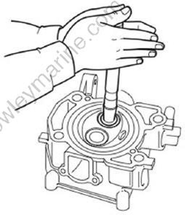
- Measure the valve seat contact width (a) where the blueing dye is adhered to the valve face. Reface the valve seat if the valve is not seated properly or if the valve seat contact width is out of specification.
Replace the valve guide if the valve seat contact is uneven.
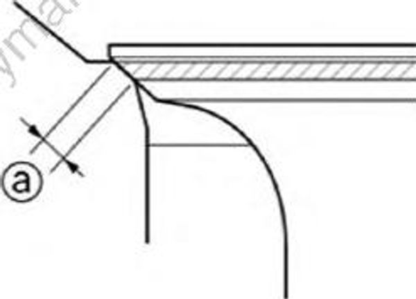
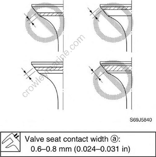
Valve seat contact width (a): 0.6-0.8 mm (0.024-0.031 in)
Refacing the valve seat
- Reface the valve seat with the valve seat cutter
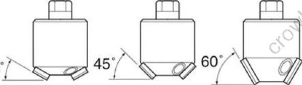
Valve seat cutter set: YB-91043-C
- Cut the surface of the valve seat with a 45° cutter by turning the cutter clockwise until the valve seat face has become smooth.
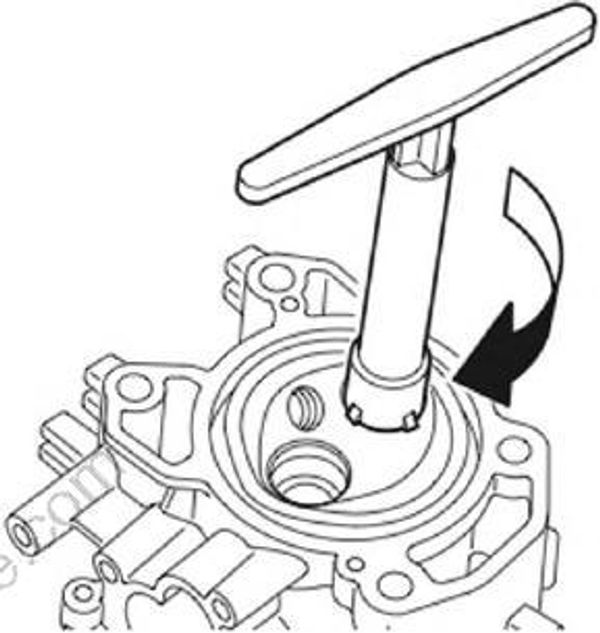
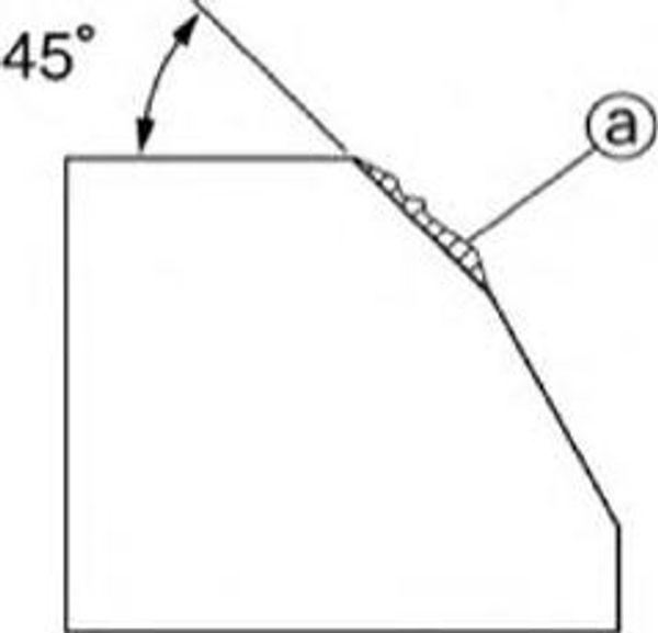
(a) Slag or rough surface
CAUTION:
Do not over cut the valve seat. Be sure to turn the cutter evenly downward at a pres sure of 40-50 N (4-5 kgf, 8.8-11 Ibf) to prevent chatter marks.
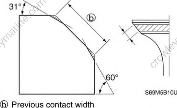
- Use a 31° cutter to adjust the contact width of the top edge of the valve seat.
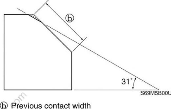
(b) Previous contact width
- Use a 60° cutter to adjust the contact width of the bottom edge of the valve seat.
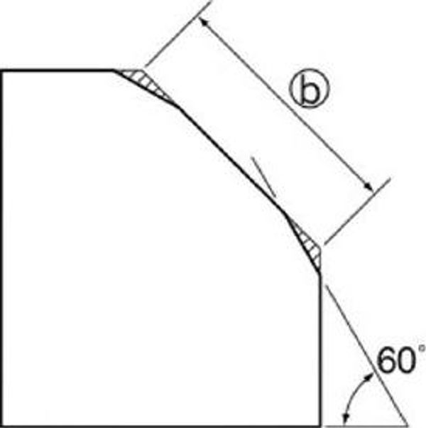
(b) Previous contact width
- Use a 45° cutter to adjust the contact width of the valve seat to specification.
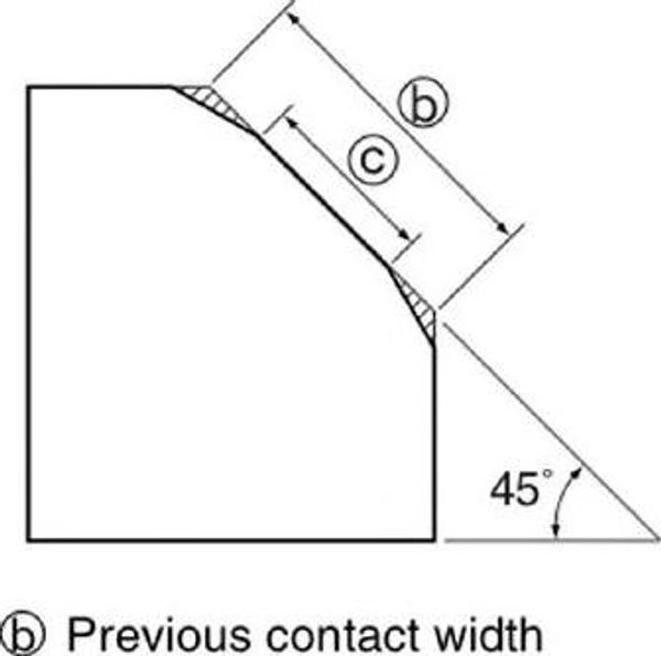
(b) Previous contact width
(c) Specified contact width
- If the valve seat contact area is too wide and situated in the center of the valve face, use a 31° cutter to cut the top edge of the valve seat and a 60° cutter to cut the bottom edge to center the area and
set its width.
(b) Previous contact width
- If the valve seat contact area is too narrow and situated near the top edge of the valve face, use a 31° cutter to cut the top edge of the valve seat. If necessary, use a 45° cutter to center the area and set its
width.
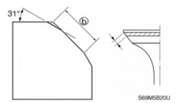
(b) Previous contact width
- If the valve seat contact area is too narrow and situated near the bottom edge of the valve face, use a 60° cutter to cut the bottom edge of the valve seat. If necessary, use a 45° cutter to center the area
and set its width.
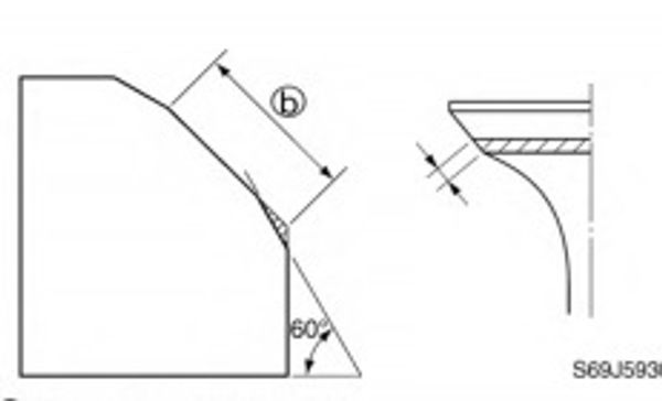
(b) Previous contact width
- Apply a thin, even layer of lapping compound onto the valve seat, and then lap the valve using a valve lapper (commercially obtainable).
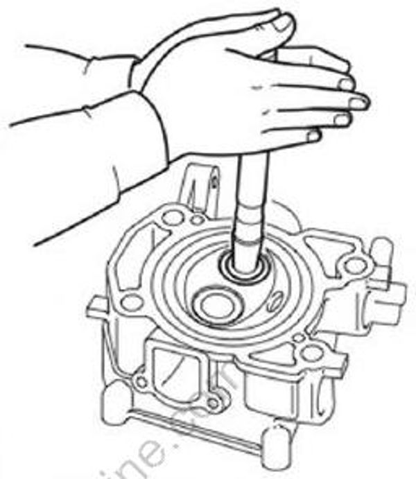
CAUTION:
Do not get the lapping compound on the valve stem or valve guide.
After every lapping procedure, be sure to clean off any remaining lapping compound from the cylinder head and the valve.
Check the valve seat contact area of the valve again.
Checking the cylinder head
Eliminate carbon deposits from the combustion chambers and check for deterioration.
Check the cylinder head warpage using a straightedge (1) and thickness gauge (2) in six directions as shown. Replace if out of specification.
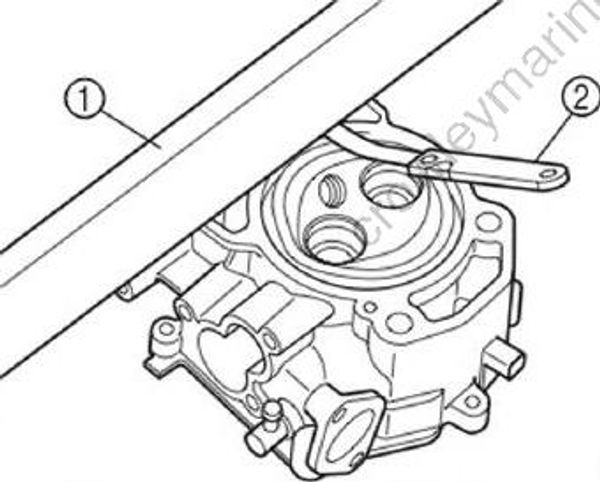
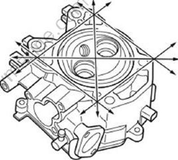
Cylinder head warpage limit: 0.1 mm (0.004 in)
Installing the valves
- Install the new stem seal (1) to the valve guide.
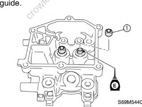
- Install the valve (2), valve spring (3), and valve spring retainer (4) in the sequence shown, and then attach the special service tool.
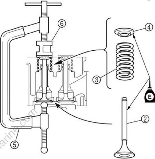
NOTE:
The valve spring can be installed in any direction.
Valve spring compressor (5): YM-01253
Valve spring compressor attachment (6): YB-06320
- Compress the valve spring, and then install the valve cotter (7) using a thin screwdriver with a small amount of grease applied to it.
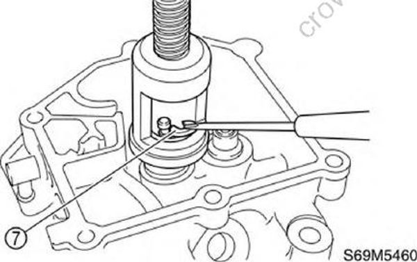
- Lightly tap the valve spring retainer with a plastic hammer to set the valve cotter securely.