

MAINTENANCE SCHEDULE
The following chart may be taken as a helpful guide to the intervals between maintenance procedures.
Initial Every | item\intervals | 10 hours | 50 hours (3 months) | 100 hours (6 months) | 200 hours ( 1 year) | Reference,page | ||||
|---|---|---|---|---|---|---|---|---|---|
| 1. | Carburetor | O | O | O | 3-25 | ||||
| 2. | Enrichment line filter | O | 3-25 | ||||||
| 3. | Fuel filter | O | O | O | 3-25 | ||||
| 4. | Fuel tank and fuel line | O | O | 3-25 | |||||
| 5. | Throttle link | O | 3-26 | ||||||
| 6. | Carburetor pick-up timing | O | 3-29 | ||||||
| 7. | Throttle sensor | O | 3-30 | ||||||
| 8. | Idling speed | O | O | 3-31 | |||||
| 9. | Spark plug | O | O | O | 3-32 | ||||
| 10. | Water drain (Engine oil tank) | O | O | O | 3-33 | ||||
| 11. | Oil injection pump | 0 | 3-33 | ||||||
| 12. | PT/T unit | O | 3-33 | ||||||
| 13. | PT/T operation | O | O | O | 3-34 | ||||
| 14. | Wiring and Connector | 0 | O | O | 3-35 | ||||
| 15. | Exhaust leakage | O | O | O | 3-35 | ||||
| 16. | Water leakage | O | O | O | 3-35 | ||||
| 17. | Lower unit leakage | O | 3-35 | ||||||
| 18. | Grease points | O | 3-36 | ||||||
| 19. | Gear oil | O | O | 3-37 | |||||
| 20. | Bolts and Nuts | O | O | O | 3-37 | ||||
| 21. | Cowling locking and releasing mechanism | O | 3-37 | ||||||
| 22. | Anode | O | O | 3-40 | |||||
| 23. | Propeller | O | O | O | 3-40 | ||||
| 24. | Motor exterior | O | O | O | 3-40 | ||||
| 25. | Battery | O | 3-41 | ||||||
| 26. | Compression pressure | O | O | O | 3-43 | ||||
| 27. | Diagnosis | O | O | O | 9-2 |
CARBURETOR
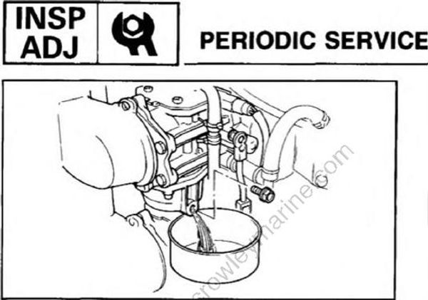
Unscrew the drain plug from each carbure tor to remove dirt and water from the float chamber.
WARNING
Put the gasoline remaining in the chamber into a proper container. The gasoline spilt
and collected in the bottom cowling may catch fire.
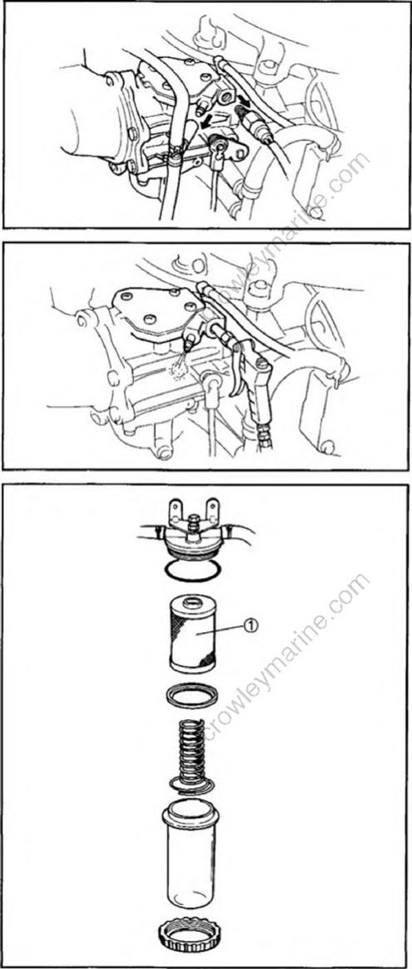
ENRICHMENT LINE FILTER
1) Remove the fuel enrichment valve and enrichment line hose from each carburetor.
2) Remove dirt from the filter by blowing each installation hole of the fuel enrichment valve with compressed air.
WARNING
Protect your eyes with suitable safety spectacles or safety goggles when using compressed air.
FUEL FILTER
Clean the strainer (1) of dust and impurities.
FUEL TANK AND FUEL LINE
1) Check the fuel tank and fuel line for leaks.
2) Clean the fuel tank thoroughly.
THROTTLE LINK
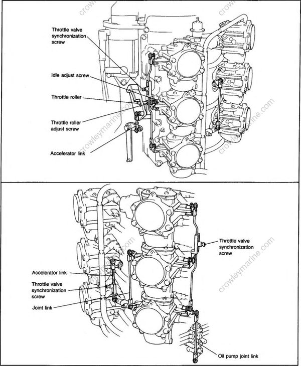
Remove the intake silencer and check that all of the throttle valves are closed when the throttle valve control lever is at fully-closed position.
In case it is not, perform the following procedure for the adjustment.
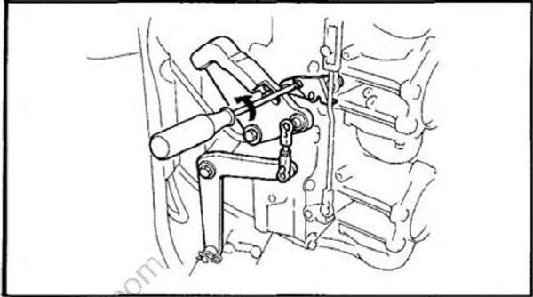
1) Loosen the throttle roller adjustment screw.
NOTE:
The screw has left-hand thread.
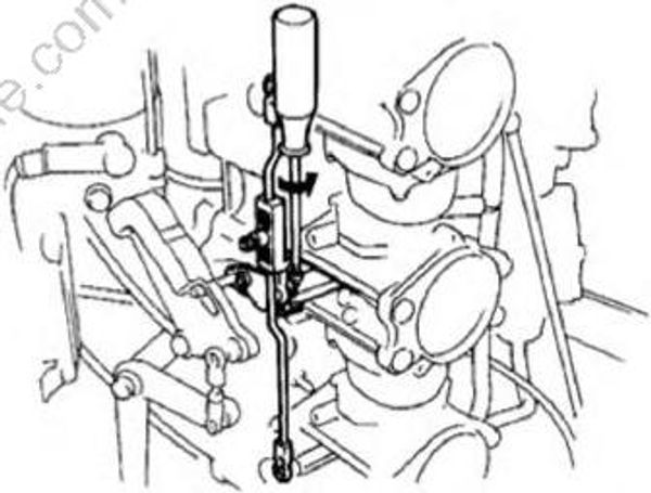
2) Turn the middle carburetor idle adjust screw on the starboard side counterclockwise until it does not touch throttle linkage.
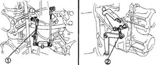
3) Disconnect the accelerator links (1) and (2) from the joint balls
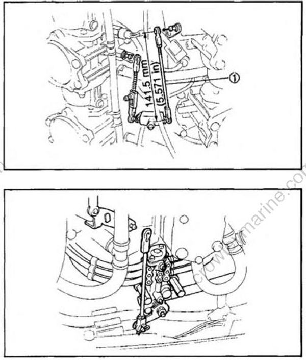
4) Remove the joint link (1), adjust the length to 141.5 mm (5.571 in) (center to center),reattach it.
5) Remove the oil pump joint link.
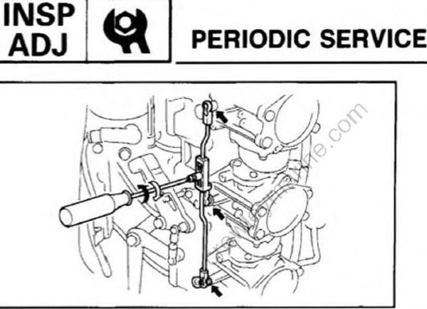
6) Loosen the throttle valve synchronization screw on each side of the motor and check that each of the throttle valves are fully closed.Retighten the screws.
NOTE:
Push the points indicated by arrows with your finger to check that each of the throttle valves is fully closed.
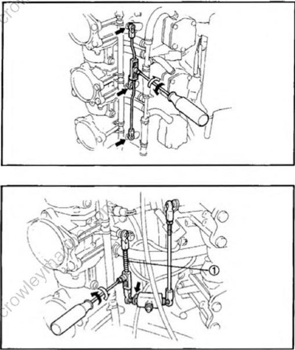
7) Connect the accelerator link (1) to the ball joint. Loosen the throttle valve synchronization screw. Keep pushing the point indicated by the arrow with your finger so that link play is out, and retighten the screw.
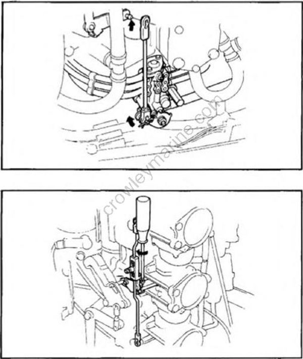
8) Hold the oil pump lever and oil pump control arm at full open position. Adjust the length of the oil pump joint link to the distance and connect it.
9) Turn the No. 4 carburetor idle adjust screw clockwise until the throttle valve starts to move. Then, turn the screw by 1 1/2 turn additionally.
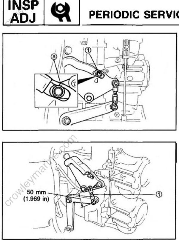
10) Adjust the throttle roller (1) installation position so the roller contacts the accelerator cam at the alignment mark (a).Then tighten the adjustment screw.
11) Adjust the length of the accelerator link (1)to 50 mm (1.969 in) (center to center) and reattach the link.
CARBURETOR PICK-UP TIMING
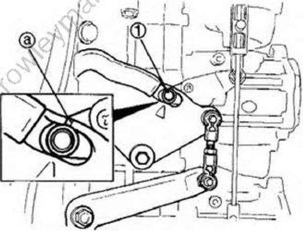
Check that the throttle roller (1) contacts the accelerator cam at the alignment mark (a). If not, adjust the position as described in the following procedure.
This adjustment is not required when the throttle link has been adjusted.
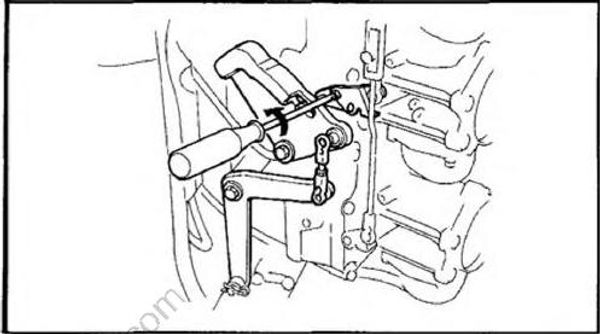
1) Loosen the throttle roller adjustment screw.
NOTE:
The screw is left-handed.
2) Adjust the throttle roller installation position so that the roller contacts the accelerator cam at the alignment mark. Then tighten the adjustment screw.
THROTTLE SENSOR
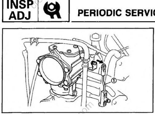
Place the throttle valve at fully closed position and remove the throttle lever rod (1) from the No. 1 carburetor.
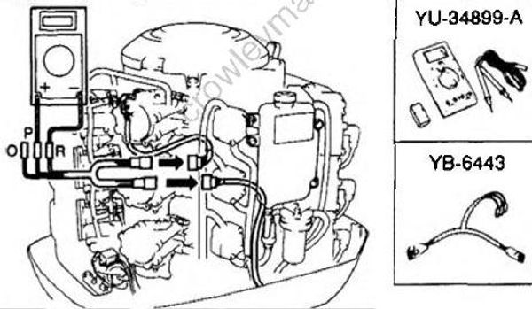
Disconnect the mating connectors of the throttle sensor and connect the adjustment harness (special tool) between the connectors.
Set the main switch to “ON” and check that the circuit tester reads a value between 0.50 and 0.52V.
When it does not, adjust the voltage as described in the following procedure.
NOTE:
Do not start the engine when these inspections and adjustments are in progress.
O: Orange
P: Pink
R: Red
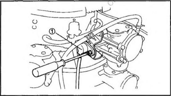
1) Remove the intake silenser.
2) Loosen the throttle sensor (1) securing screws.
3) Turn the sensor clockwise until the circuit tester reads the following specification. Then, tighten the screws.
Output voltage: 0.51 ± 0.01V
NOTE:
When the voltage is reduced below 0.50V, return the sensor to the position where the voltage becomes over 0.52V, and repeat the above adjustment 2), 3) again.
IDLING SPEED
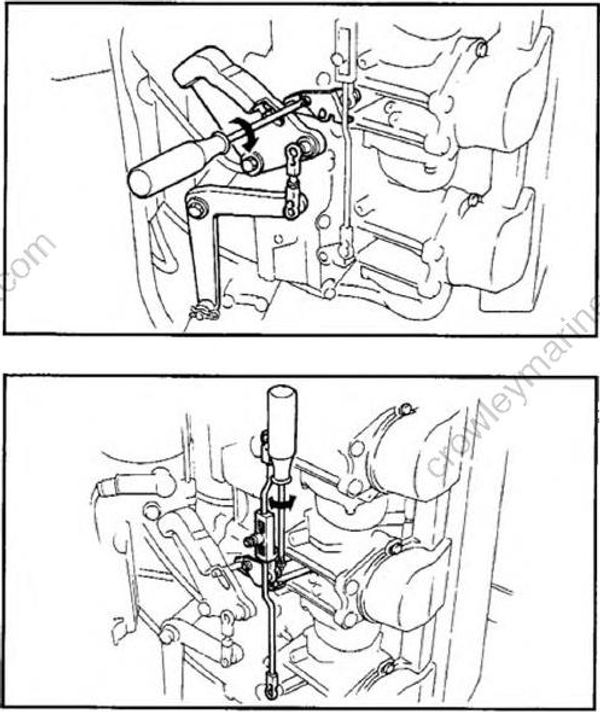
NOTE:
Complete the procedure described in 5. THROTTLE LINK before checking idling speed.
Check (adjust) the throttle link.
Start the engine, warm it up and then check the RPM. If it is out of the specification, adjust the idling speed described in the following procedure.
Idling speed: 675 ~ 725 rpm
1) Loosen the throttle roller adjustment screw.
NOTE:
The screw is left-handed.
2) Turning the idle adjustment screw of the No. 4 carburetor and adjust the throttle opening angle so that the idling speed stays within the specifications.
3) Adjust the carburetor pick up timing.
NOTE:
Never turn the pilot screw to adjust the idling speed.
SPARK PLUG
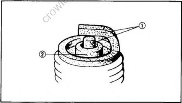
1) Check the electrode (1) for evrosion, note the insulator (2) color and the electrode gap.
Normal condition is a medium to light tan color.
Distinctly different color -» Check the engine condition.
White color : Lean fuel mixture
- Plugged filter, jet
- Air leak
- Wrong settings
Blackish color: Electrical malfunction
- Defective spark plug
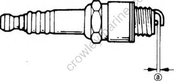
2) Clean the spark plug with spark-plug
cleaner or wire brush. Use a wire gauge
to adjust the plug gap (a) to specification.
Spark plug gap: 0.9 ~ 1.0 mm (0.035 ~ 0.039 in)
3) If the electrode is eroded excessively,replace the spark plug.
Standard spark plug:
BR8HS-10
4) When installing the spark plug, clean the gasket surface, wipe off any grime there
may be on the surface of the spark plug,and tighten the spark plug to the specified torque.
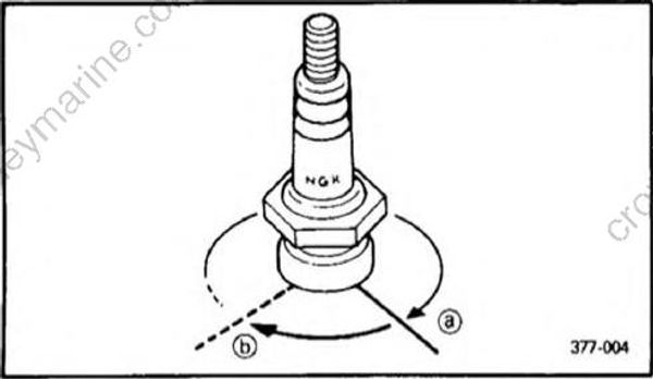
Tightening torque: 25 Nm (2.5 m*kg, 18 ft lb)
NOTE:
If a torque wrench is not available finger tighten the spark plug first (a) and then
tighten it by 90 degree (b) using the spark plug wrench.
ENGINE OIL TANK
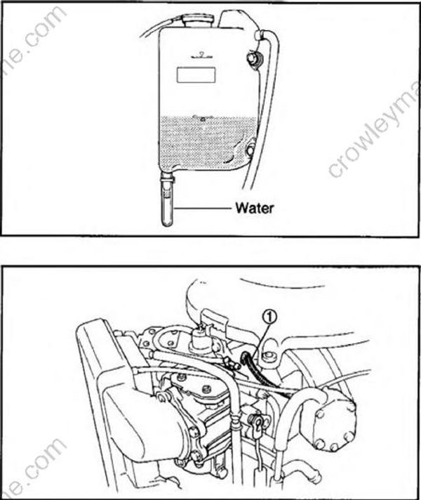
WATER DRAIN (ENGINE OIL TANK)
1) When water or foreign matter collects in the translucent cap of engine oil tank, remove the cap immediately and drain it off.
OIL INJECTION PUMP
1) Start the engine, disconnect an oil delivery hose (1) from the intake manifold and check that the oil runs out of the hose.
CAUTION:
Use 50 : 1 pre-mixed fuel to prevent engine seizure.
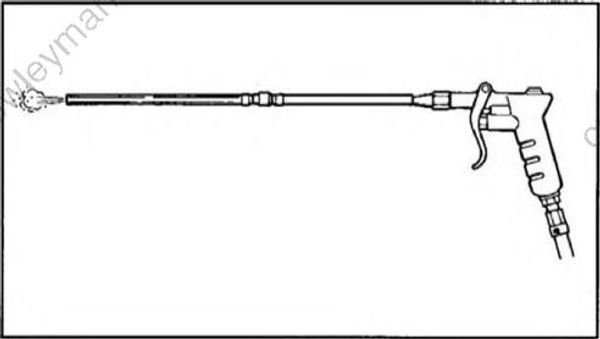
2) In case it does not, stop the engine, remove the delivery hose, blow the hose at pump side by means of the com pressed air, and then repeat the above procedure.
NOTE:
Blowing from intake manifold side will not run the air because of blocking by a check valve on the delivery hose.
PT/T UNIT AND OPERATION
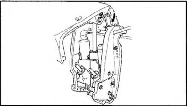
1) Check that no oil leaks from the connec tion point of the pipe and from the gaps between tilt rod or trim rods and the oil seals.
2) Check that the tilt rod and trim rods are free of flaws and salt.
3) Tilt-up the motor, and lock it with the tilt-lock lever.
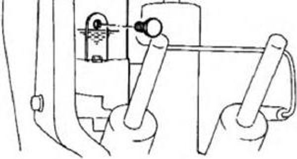
4) Remove the fluid-level plug to check the fluid level, with the motor tilted-up. The fluid level should be immediately below the fluid level-hole. If the fluid level is low, top up with the recommended fluid.
5) Re-fit the fluid-level plug, and tighten it.
Recommended fluid: Yamaha power trim and tilt fluid
PT/T OPERATION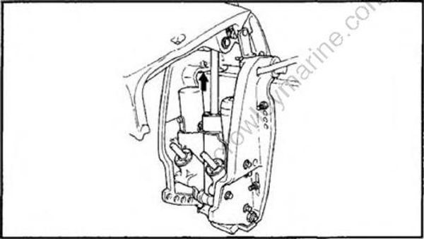
1) Tilt up the motor and check that the tilt rodand the trim rods are pushed out
completely.
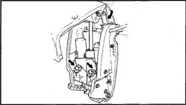
2) Lock the motor with the tilt-lock lever.Activate the tilt-down switch to check that
the trim rods are put in the cylinder.
3) Activate the tilt-up switch. Unlock the tilt lock lever when the trim rods have been
fully pushed out.
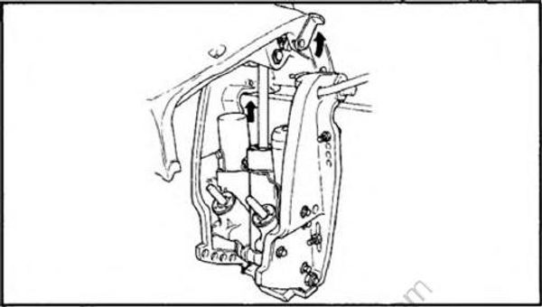
4) Activate the tilt-down switch to check that both the trim rods and the tilt rod
are retracted into the cylinders completely and smoothly.
WIRING AND CONNECTOR
1) Check that each grounding wire is secured.
2) Check that each connector is engaged securely.
EXHAUST LEAKAGE
Start the engine and check that no exhaust leaks from the joints between the exhaust cover, cylinder head and crank case.
WATER LEAKAGE
Start the engine and check that no water leaks from the joints between the exhaust cover, cylinder head and crank case.
LOWER UNIT LEAKAGE
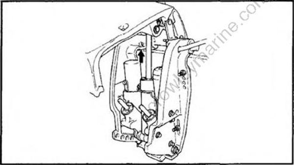
1) Tighten the gear-oil-drain screw, and con nect the tester to the oil-level hole.
2) Pump the tester to apply a specified pressure.
3) Check that the pressure is held at specified pressure for 10 seconds.
70 kPa (0.7 kg/cm2, 9.96 psi)
NOTE:
Do not overpressurize. If excess pressure is used, air may leak out.
If the pressure falls, the leakage from lower unit is unacceptable, requiring re inspection of its component parts.
GEAR POINTS
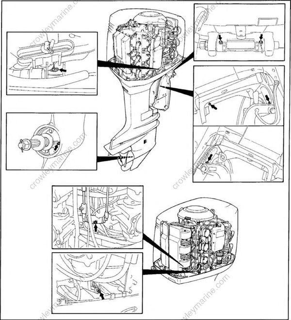
Inject grease through each greasing nipple.
GEAR OIL
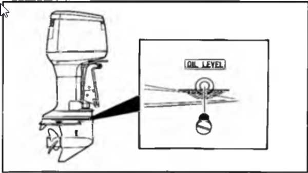
1) Drain the gear oil thoroughly, and pour new oil.
2) Check for water or metallic sediment in the drained oil.
NOTE:
If the gear oil becomes ’milky’, check the gear case oil seals for water entry.
Because of the two-piece propeller shaft used on counter rotation models, molybde num disulphide (’moly’) grease is used at various points during factory assembly.
When this grease mixes with lower unit gear oil, discoloration of the oil occurs. It may even turn the oil black.
This condition is normal, and discoloration may continue over several oil changes.
Recommended oil:
GEAR CASE LUBE (USA) or Hypoid gear oil SAE #90
Oil capacity: 225, 250: 1,150 cm (38.9 US oz, 40.5 Imp oz)
L225, L250: 1,000 cm3 (33.8 US oz, 35.2 Imp oz)
BOLTS AND NUTS
1) Check that bolts securing the cylinder head and engine and the nut securing the flywheel are not loose.
2) Check the other bolts and nuts are not loose.
COWLING LOCKING AND RELEASING MECHANISM
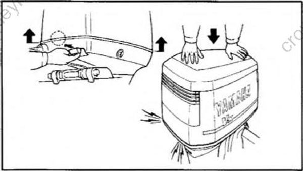
Cowling release and lock
1) Check the cowling release and lock mecha nism for functioning.
Wire adjustment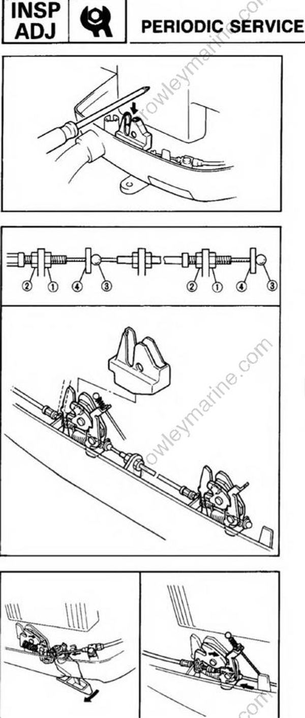
1) Push each locking plates down until the lock goes to locking state.
2) Turn nut A and then nut B of the rear lock as indicated until both wire ends touch the plates.
- (1) Nut A
- (2) Nut B
- (3) Wire end
- (4) Plate
CAUTION:
Do not apply tension to the wire, or weak engagement of the lock may result.
3) Tighten both nuts after the adjustment.
4) Pull the cowling release lever to check that both of the locks go to releasing state.
Cowling hook adjustment
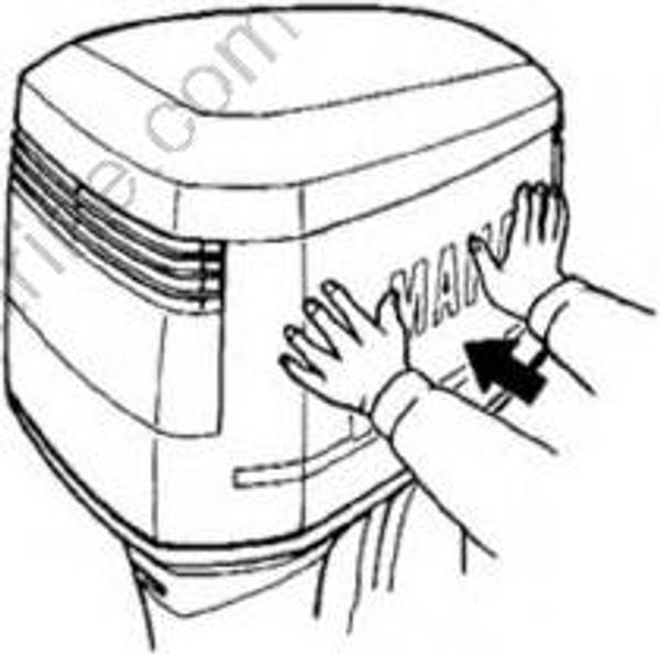
1) Push the top cowling sideways lightly. The following position adjustment is required if a gap is made between top and bottom cowlings.
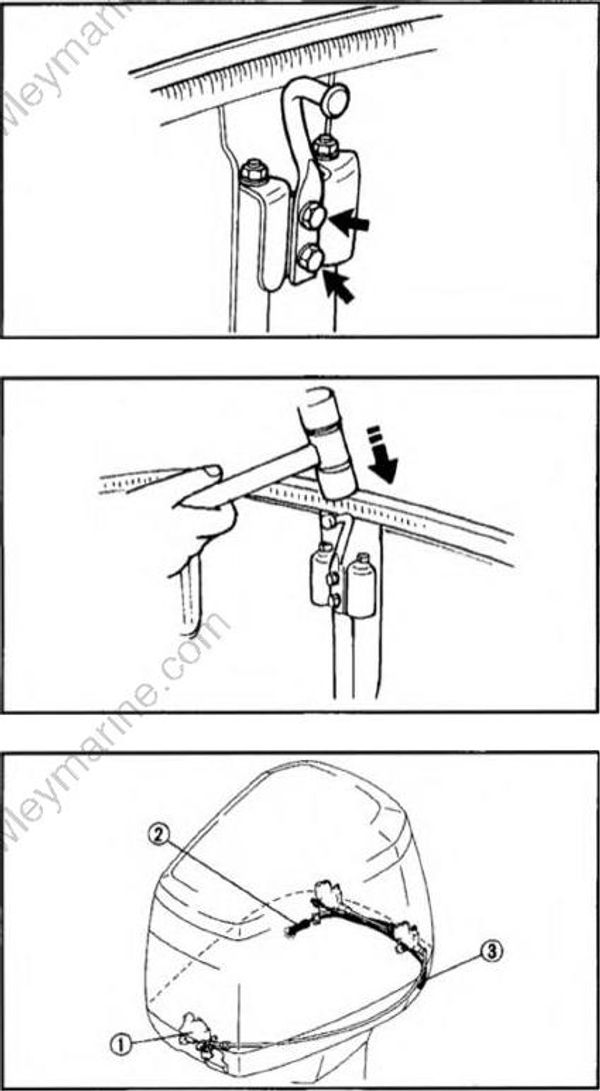
2) Loosen two bolts by approximately a quarter turn.
3) Tap the end to make an appropriate move. Tighten the bolts, replace the top cowling and then check the engagement. Repeat the adjustment if necessary.
NOTE:
Moving latch towards seal will loosen cowling, moving latch a way from seal (as shown) will tighten cowling.
Emergency releasing
In case the cowling release lever (1) will not function, the cable may be damaged or mis-adjusted.
1) Pull the emergency cowling release wire (2) coming out of the hole on the side of the pilot hole in the bottom cowling to actuate the port side rear lock.
2) Open the port side of the top cowling to pull out the emergency cowling release wire (3) from the port side of the bottom cowling.
3) Pull the emergency cowling release wire (D to actuate the starboard side rear lock.
CAUTION:
Be sure the cowling lock is properly adjusted before reinstalling the cowling.
ANODE
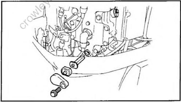
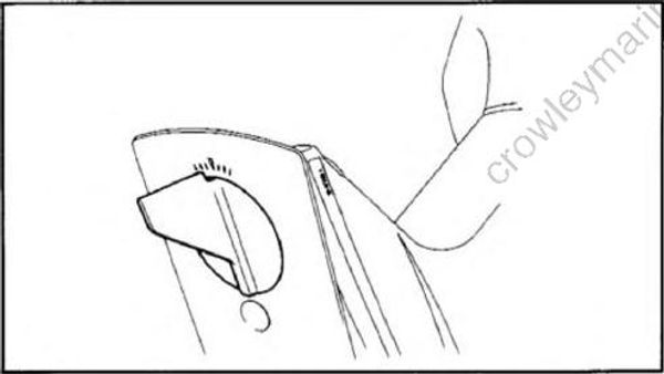
Inspect the anode. If it is consumed, replace it with a new one. If scaling of the surface is evident, remove the anode and clean it with a wire brush, and remove all trace of oil or grease. After cleaning, polish the contact surfaces of the anode mount, and install it.
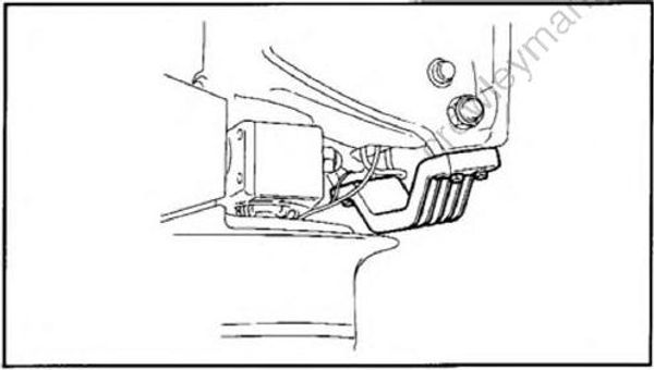
CAUTION:
Do not paint the anodes, or the function will be impaired.
PROPELLER
1) Check the blades for wear, damage, cavitation erosion.
2) Check the splines for wear and damage.
MOTOR EXTERIOR
Check the motor for paint flaking on the exterior. If necessary, paint the areas with original color.
BATTERY
WARNING
Battery electrolyte contains sulphuric acid which is poisonous and corrosive, i.e., it can cause skin burns and damage to eyes. Avoid all contact with the skin, eyes, or clothing.
First Aid:Eyes: flush with water for fifteen minutes (if necessary holding the eye open with clean fingers), and get prompt medical attention.Internal: Do not make the casualty vomit.Give plenty of water to dilute the acid. Add if possible, 2 tablespoons of chalk, milk of
magnesia, plaster or whitewash to a pint of water.
Skin burns: Thoroughly flood the part with water. Remove contaminated clothing.
Bathe the part in an alkaline solution such as two teaspoons of baking soda (bicarbonate of soda) or washing soda (carbonate of soda) to one pint of warm water.
Batteries produce explosive gases. Keep sparks and flames away. Do not smoke where batteries are charged or stored. Ventilate the area when charging or using batteries in any enclose space.
KEEP BATTERIES AND ELECTROLYTE OUT OF THE REACH OF CHILDREN
Recommended battery capacity: 12V, 100 AH (360 kC)
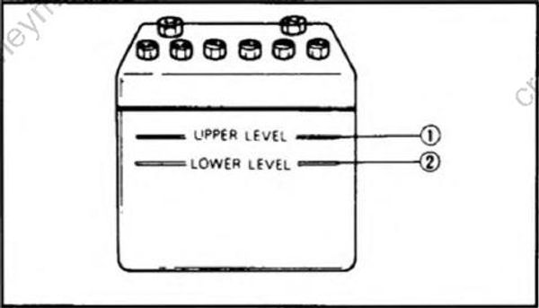
1) The electrolyte level should be between the upper and lower level marks. Use only distilled water if refilling is necessary.
CAUTION:
Normal tap water contains minerals which are harmful to the battery, therefore, refill only with distilled water.
(1) Upper level
(2) Lower level
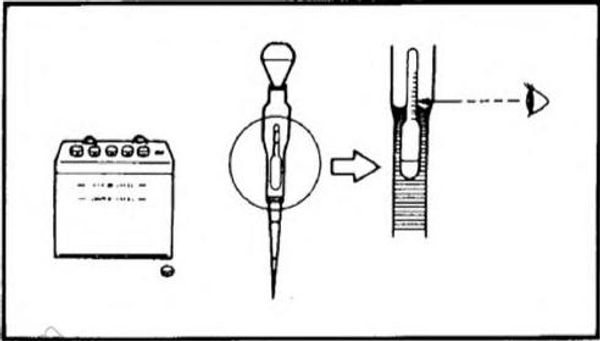
2) Before first use, the battery must receive its initial electrical charge.
CAUTION:
The battery must be charged before use to ensure maximum performance.
Failure to charge the battery properly before first use or a low electrolyte level will cause premature failure of the battery.
Charging:
Charge at 10.0 amperes for 10 hours or until the specific gravity of electrolyte reaches 1.260 at 20°C (68°F).
3) Thoroughly clean the battery terminals, and tightly connect the leads to the terminals.
Lightly coat the terminals and connectors with petroleum jelly.
CAUTION:
Turn off the main switch before checking or replacing the battery.
When installing the battery connect the positive terminal (red lead) first.
When removing the battery disconnect the negative terminal (black lead) first.
NOTE:
Replace the battery if:
The voltage does not rise to an open-circuit value of at least 2.2 volts per cell, or no bubbles are seen even after many hours of charging;
The plates show a whitish color, or there is an accumulation of material in the bot tom of the cell, indicating sulphation on one or more cells.
Specific gravity readings after a long slow charge indicate one or more cells to be lower than the rest;
There is visible warping or buckling of plates or insulators in any cell.
COMPRESSION PRESURE
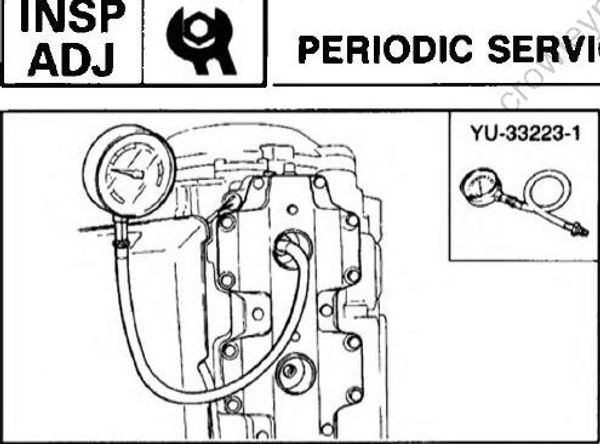
1) Run the engine for longer than 5 minutes till it warms up.
WARNING
Disconnect emergency stop plate before cranking to prevent ignition system from operating and engine from tarting.
2) Remove the spark plug from all cylinders.
3) Attach the compression gauge to the spark plug hole and measure the compression pressure of each cylinder to check that it is within the specified range.
NOTE:
Perform cranking for at least 3 seconds at wide open throttle till the gauge pointer is stable.
Compression pressure:
250 : 580 ~ 730 kPa
(5.8 ~ 7.3 kg/cm2 82.5 ~ 103.8 psi)