

DUAL BATTERY CHARGING SYSTEM (OPTION)
If installing the battery isolator lead assembly, available as optional parts, and changing the position of 40 A fuse from standard to option, dual battery charging system will be effective. Be sure to check if the optional 40 A fuse in OPT position is blown, when the second battery for accessories will not be charged.
Please ask your authorized Suzuki Marine Dealer for installation of the isolator lead assembly.
USE OF ELECTRICAL ACCESSORIES
The amount of power (12V DC) available for accessories depends on the operating condition of the motor. For getting a detailed information, please inquire of your authorized Suzuki Marine Dealer.
Use of too much power for electrical accessories under certain operating conditions can cause the battery to discharge.
SUZUKI KEYLESS START SYSTEM (IF EQUIPPED WITH KEYLESS START SYSTEM)
This system allows you to start the engine by means of communication between the key-fob and the keyless control unit when you have the key-fob with you, instead of using the mechanical key.
The engine can be started when the distance between the key-fob and the keyless control unit is within the communication range of 1 m (39.4 in.).
In addition, this system is equipped with immobilizer feature.

Please consult with a Suzuki Marine Dealer for the installation of the Keyless Start System.
Also refer to the “Keyless Start System Instruction Manual” supplied with the product for detailed operating instructions.
IMMOBILIZER SYSTEM
In this system, the key-fob and the keyless control unit uses radio communication to check if the key-fob ID is registered in the Keyless Start System.
If the key-fob ID is not registered, the system prevents the engine from starting using the key fob.
Radio waves from the keyless control unit may interfere with the operation of electrical medical equipment such as pacemakers. Failure to take the precautions listed below can increase the risk of severe injury or death due to radio wave interference.
Anyone who uses electrical medical equipment such as a pacemaker should consult the medical equipment supplier to inquire if radio waves from the keyless control unit can interfere with the medical equipment.
KEY-FOB
Two (2) key-fobs are supplied with the Keyless Start System.

The key-fob emits radio waves that may interfere with aircraft operations.
Do NOT operate the buttons on the keyfob while you are in flight. When putting the key-fob in a bag, etc., protect the buttons from accidently being pressed.
The key-fob falls under the category of restricted electronic devices for use in flight.
The radio waves emitted from the key-fob may cause interference with other wireless communication devices such as mobile phones and remoter controllers.
Do not operate the buttons on the key-fob more than necessary.
Attempting to disassemble (except for battery replacement), repair, or modify the key-fob may cause ignition, electric shock, or injury.
Do NOT attempt to disassemble (except for battery replacement), repair, or modify the key-fob.
The key-fob is comprised of sophisticated electronic components that can become damaged and may fail to function properly if you do not take proper precaution.
• Do NOT leave it in places that may reach a high temperature.
• Do NOT apply a strong impact, such as dropping it.
• Do NOT bring it close to any magnetic objects.
• Do NOT place it near any electro-magnetic devices such as a television or audio equipment.
• Do NOT place it near any electric medical equipment (microwave therapy equipment, low frequency therapy equipment, etc.), or receive medical treatment with the key-fob in your pocket, etc.
• Do NOT erase or tamper with the conformance certification mark.
• A maximum of six (6) key-fobs can be registered in one keyless control unit.
• The battery life of the key-fob is about two (2) years, which can vary depending on use.
• The key-fob is always in transmission mode in order to communicate with the keyless control unit. For this reason, the battery may run down quickly if it receives strong radio waves from televisions or personal computers, etc.
• The emergency key should be carried separately from the key-fob to avoid losing both of them at the same time.
• If the key-fob and the emergency key are lost, immediately contact your authorized Suzuki Marine Dealer.
• The key-fob uses a weak radio wave that is susceptible to external influences when it communicates with the keyless control unit. For this reason, it may not operate properly under the following use environment.
– There is a nearby facility that emits strong radio waves such as a television tower, electric power plant, or broadcasting station, etc.
– The key-fob is held close to other wireless communication devices such as mobile phone, radio equipment or a laptop personal computer.
– The key-fob is in contact with or covered with a metallic object.
One (1) emergency key is included in the main switch panel for the Keyless Start System.
Switching the communication mode of the key-fob
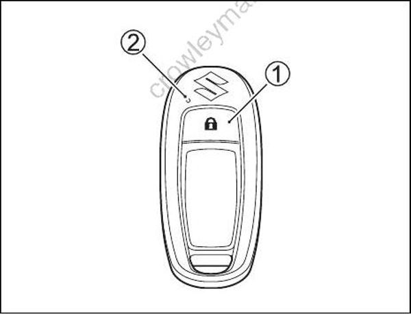
Press and hold the lock button (1) on the key-fob for more than one second to switch between ON mode and OFF mode.
If the lock button is pressed briefly while in communication ON mode, the LED (2) on the keyfob briefly flashes once.
KEY-FOB BATTERY REPLACEMENT
This product contains a coin/button cell battery. If swallowed, the coin/button cell battery can cause severe internal burns in just 2 hours and may lead to death.
• THE BATTERY IS A CHEMICAL BURN HAZARD. DO NOT INGEST THE BATTERY. If you think batteries might have been swallowed or placed inside any part of the body, seek immediate medical attention.
• Keep new and used batteries away from children. If the battery compartment cannot be closed securely, stop using this product and keep it away from children.
There is a danger of explosion if the battery is replaced with an incorrect type.
Only replace the battery with the same or equivalent type.
Do not expose Hand Unit to excessive heat such as from sunlight or fire.
To prevent damage to the key-fob, be careful when replacing the battery.
• Install the lithium disc-type battery with the electrodes facing the proper direction.
• Do NOT touch the internal circuit of the key-fob when replacing the battery.
If the key-fob battery runs low, “Remote Key Battery Low” appears on the gauge, which indicates the battery should be replaced.

To replace the key-fob battery:
- Insert a flat blade screwdriver in the slot of the key-fob and remove the cover.

- Remove the O-ring (1).

The O-ring may be fitted on the cover side.
If the O-ring is damaged, the waterproof performance deteriorates, which can cause the key-fob to malfunction.
Be careful not to damage the O-ring when removing it.
- Insert a flat blade screwdriver into the slot at △ mark on the cover to remove the battery.

- Replace the battery so its (+) terminal faces the cover side as shown in the illustration. Lithium disc type battery: CR2025 or equivalent.
Confirm that the O-ring is placed in position on the body side.

- Reinstall the cover.
SETTING AND/OR CHANGING THE PASSCODE
By setting a 4-digit passcode, the engine can be started by entering the passcode even if the key-fob battery has run down or the key-fob is lost.
The same method is used to set and change the passcode.
Carry the passcode with the emergency key in case the key-fob battery runs down or the keyfob is lost.
When the passcode has been updated or changed, the previous passcode is deleted and updated to the new passcode.
Use the following procedure to set or change the passcode:
Confirm the engine is stopped.
Make sure the emergency switch lock plate is in place.
Confirm the key-fob is within the communication range of the Keyless Start System.
Confirm that the key-fob is in communication
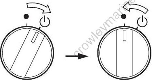
ON mode. (Refer to “Switching the communication mode of the key-fob” section.)Turn the main switch to the position and then release it. The main switch automatically returns to the position. The buzzer on the engine control side emits one (1) long sound while the buzzer on the keyless control unit side emits two (2) short sounds simultaneously.
- Pull out the emergency stop switch lock plate.

- Within eight (8) seconds after performing Step 5, start the following operation. (1)Turn the main switch to the position and hold it for about five (5) seconds then release it to the position.
Repeat this operation for two more times. The buzzer sounds once and the system
enters stand-by mode for passcode input.
The buzzer will not sound if the operation in Step (1) is not performed within eight (8) seconds or the operation fails.

(2) Within 60 seconds after performing Step (1), turn the main switch to the position and then release it. The main switch automatically returns to the position.
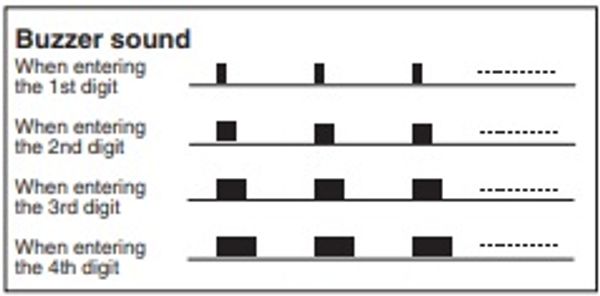
The buzzer starts emitting short sounds. Briefly turn the switch after the number of sounds that is the same as the first passcode digit. For example, if the first passcode digit is seven, turn the switch after the seventh sound.
To set or select zero (0), turn the switch after the 10th sound.
If the operation in Step (2) is not performed within 60 seconds after performing Step (1), the passcode input operation will be cancelled and
the buzzer will sound three (3) times.

After the buzzer emits 10 sounds, it emits one long sound before to returning to stand-by mode for the second passcode digit.
(3) Repeat Step 2 to enter the second, third and fourth passcode digits.
(4) After entering the fourth pass code digit, the buzzer emits one continuous sound – within 60 seconds, turn the switch ON and hold it for five (5) seconds until the buzzer stops, then release it.
The buzzer emits one (1) short sound for the 1st digit, two (2) short sounds for the 2nd digit, three (3) short sounds for the 3rd digit, and four
(4) short sounds for the 4th digit.
• If a passcode is not entered during the 10 sounds, the process will start over again after briefly turning the switch.
• If the main switch is not turned to select a passcode number after repeating the passcode input operation three (3) times, the input operation is cancelled.
In this case, the buzzer emits short beeps for five (5) seconds to notify that the input operation has been cancelled.
• If the passcode input operation has been performed multiple times, the last passcode entered will become effective.
• To interrupt passcode input, install the lock plate on the emergency stop switch.

When performing the passcode input operation again after the operation has been cancelled due to passcode input failure or after having interrupted the operation;
1) Install the emergency switch lock plate.
2) Turn the main switch to the position and then release it to the
position.
3) Perform the procedure described above from Step 5.
(5) After the buzzer has sounded once, the keyfob LED will blink the entered passcode.

(6)Install the lock plate on the emergency stop switch.
(7)Turn the main switch to the position and then release it to the position to turn the Keyless Start System OFF.
After that, do not perform any operation for at least 30 seconds, while the system performs passcode update.
PASSCODE CONFIRMATION
Confirm that the engine is stopped.
Make sure the emergency switch lock plate is in place.
Confirm the key-fob is within the communication range of the Keyless Start System.
Confirm the key-fob is in ON mode. (Refer to “Switching the communication mode of the key-fob” section.)
Turn the main switch to the position and then release it. The main switch automatically returns to the position.
The buzzer on the engine control side emits one (1) long sound while the buzzer on the keyless control unit side emits two (2) short sounds simultaneously.

- Within eight (8) seconds after performing Step 5, start the following operation.
(1) Turn the main switch to the position and hold it for five (5) seconds or longer, then release it to the position.
Repeat this operation for two more times.

(2)The LED on the key-fob blinks once and the buzzer sounds once.
After that, the LED on the key-fob blinks to indicate the passcode by the number of blinks, as shown in the illustration. This is indicated repeatedly.
The passcode indication will not start if Step (1) is not performed within eight (8) seconds or the operation fails.
In this case, turn the main switch to the position and then release it to the position to turn the Keyless Start System OFF. After that, retry the procedure from Step 5.

- After the passcode confirmation is completed, turn the main switch to the position and then release it. The main switch automatically returns to the position. The Keyless Start System turns OFF and the passcode indication stops.
PROPELLER SELECTION, INSTALLATION AND REMOVAL
PROPELLER SELECTION
It is essential to use a propeller on your outboard motor that is properly matched to your boat’s operating characteristics. The speed of the engine when you operate your boat at full throttle depends on the propeller you use. Excessive engine speed can seriously damage the motor, while low engine speed at full throttle will adversely affect the performance. Your operating load will also affect propeller selection. Smaller loads generally require larger pitch propellers; larger loads generally require smaller-pitch propellers. Your authorized Suzuki Marine Dealer will assist you in selecting a suitable propeller for your boat.
Installing a propeller with either too much or too little pitch will cause incorrect maximum engine speed, which may result in severe damage to the motor.
Consult your authorized Suzuki marine dealer to assist you in selecting a suitable propeller for your boat.
You can determine if your propeller is appropriate for use with your boat by using a tachometer to measure engine speed when operating your boat at full throttle, under minimum load conditions. If you are using an appropriate propeller, the engine speed will be within the following range:
| DF350A | 5700 - 6300 r/min. (min–¹) |
|---|
If the engine speed is not within this range, consult your authorized Suzuki Marine Dealer to determine which propeller size is best for you.
If you change propellers, be sure to perform the above check again, to confirm that the engine speed under full throttle is within the specified range.