

DIAGNOSTIC SYSTEM
Water and wind conditions permitting, stop the motor, tilt it out of the water and remove any debris like seaweed, plastic bags or sand that may have blocked the water intakes.
Lower the motor into the water, being sure that water intakes are immersed, and restart it.
Check (A) that water discharges from the pilot hole and (B) that the red TEMP lamp is no longer lit.
Be aware that the red TEMP lamp may light again if engine temperature rises abnormally. If either of the above situations arises, your authorized Suzuki Marine Dealer must be consulted as soon as possible.
Operating the engine with the Cooling Water Caution System activated can result in severe engine damage.
If the Cooling Water Caution System activates, stop the engine as soon as possible, wind and water conditions permitting, and inspect the engine according to the above instructions. Consult your authorized Suzuki marine dealer if you cannot correct the problem.
If the engine is operated beyond the maximum trim position, the water intake holes may be above the water line. In this situation, the cooling water caution system may activate.
If abnormal conditions exist in any sensor signal being sent to the control unit, the self-diagnostic system warns of the abnormal condition.
TILLER HANDLE MODEL
If this system activates, the CHECK ENGINE lamp will flash.
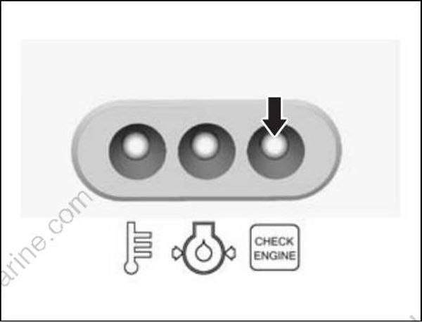
Also incorporated is a fail-safe provision that allows the operation at a restricted speed even under such a failure condition.
The buzzer sound with diagnostic system activating will be stopped after approx. thirty seconds.
Ignition key is turned to the “ON” position, when engine is not running.
If this system activates, the CHECK ENGINE lamp will flash.
Also incorporated is a fail-safe provision that allows the operation at a restricted speed even under such a failure condition.
• The CHECK ENGINE lamp will light briefly when the ignition key is turned to the “ON” position.
• The failed system can be identified by the mode of the CHECK ENGINE lamp flashing.
This diagnostic code is designed to appear while the ignition key is turned on.
OIL CHANGE REMINDER SYSTEM
This system informs the operator of the time for replacing engine oil on the basis of the maintenance schedule.
The system is designed to register the total operating hours of the outboard motor and function its operation when the preprogrammed hours have reached.
(Refer to the INSPECTION AND MAINTE NANCE section and the last page.)
SYSTEM ACTIVATION
TILLER HANDLE MODEL
When the total operating hours have reached the preprogrammed hours, the red OIL lamp will flash while the engine is running. This indication will repeat until you cancel the system activation.
REMOTE CONTROL MODEL
When the total operating hours have reached the preprogrammed hours, the red OIL lamp will flash and a buzzer will sound. This OIL lamp indication will repeat until you cancel the system activation.
The buzzer sound will be stopped after approx. thirty seconds.
Ignition key is turned to the “ON” position while engine is not running.
This system activates, the red OIL lamp will flash but no buzzer sound. This OIL lamp indication will repeat until you cancel the system activation.
CANCELLATION
TILLER HANDLE MODEL
- Start the motor.
Make sure that the motor is in “Neutral” and the throttle grip is fully closed.
The engine stops when the engine stop button is kept to push more than 0.5 seconds.
- Push the engine stop button (1) three times within three seconds so that the engine should not stall.
The red OIL lamp is no longer lit when the reminder cancellation is successful.