

EXPLODED DIAGRAM
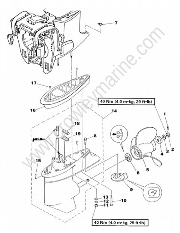
REMOVAL AND INSTALLATION CHART
| Step | Procedure/Part name | Q'ty | Service points |
|---|---|---|---|
| LOWER UNIT REMOVAL | Follow the left "Step" for removal | ||
| 1 | Cotter pin | 1 | |
| 2 | Propeller nut | 1 | |
| NOTE: If the propeller nut does not align with the propeller shaft hole when the nut is tight |
|||
| 3 | Plane washer | 1 | |
| 4 | Spacer | 1 | |
| 5 | Propeller | 1 | |
| 6 | Spacer | 1 | |
| 7 | Cap | 1 | |
| 8 | Bolt (with washer) | 1 | |
| 9 | Trim tab | 1 | |
| NOTE: Be sure to align the line on both the trim tab and anti-cavitation plate. |
|||
| 10 | Bolt (with washer) | 1 | |
| 11 | Nut | 4 | |
| 12 | Spring washer | 4 | |
| 13 | Plate washer | 4 | |
| 14 | Lower unit assembly | 1 | |
| NOTE: Insert the drive shaft into the crankshaft. If the splines will not come in complete mesh, rotate the propeller shaft a little so that they are in mesh correctly |
|||
| 15 | Dowel pin | 2 | |
| 16 | Extension | 1 | |
| 17 | Dowel pin | 2 | |
| 18 | Seal damper | 1 | |
| 19 | Seal damper guide | 1 | |
| Reverse the removal steps for installation |
Propeller inspection
- Inspect:
- Blade
- Spline
Wear/Crack/Damage -> Replace