

LOWER UNIT
EXPLODED DIAGRAM
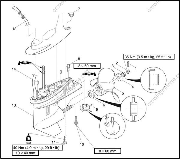
REMOVAL AND INSTALLATION CHART
| Step | Procedure/Part name | Q'ty | Service points |
|---|---|---|---|
| LOWER UNIT REMOVAL | Follow the left "Step" for removal. | ||
| 1 | Cotter pin | 1 | |
| 2 | Propeller nut | 1 | |
| 3 | Spacer | 1 | |
| 4 | Washer | 1 | |
| 5 | Propeller | 1 | |
| 6 | Thrust washer | 1 | |
| 7 | Cap | 1 | |
| 8 | Bolt | 1 | |
| 9 | Trim tab | 1 | |
| Mark the original position (a) for proper installation |
EXPLODED DIAGRAM
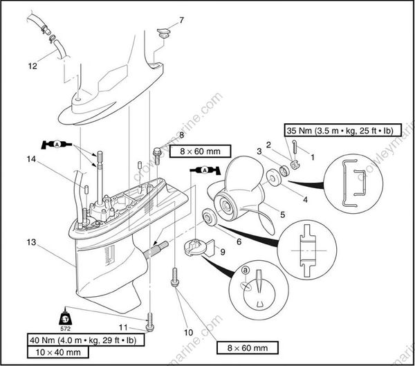
| Step | Procedure/Part name | Q'ty | Service points |
|---|---|---|---|
| 10 | Bolt | 1 | |
| 11 | Bolt | 4 | |
| 12 | Speedometer hose | 1 | |
| 13 | Lower case | 1 | |
| 14 | Pin | 2 | |
| Reverse the removal steps for installation. |
Service Points
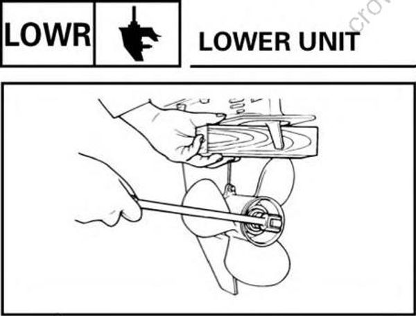
WARNING
Do not hold the propeller with your hands when removing or installing it. Put a block of wood between the anti-cavitation plate and propel
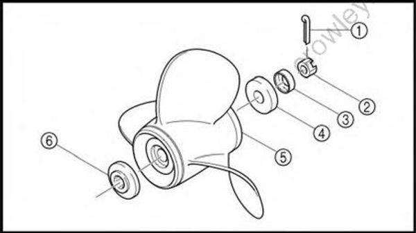
Propeller removal
- Remove:
- (1)Cotter pin
- (2) Propeller nut
- (3) Spacer
- (4) Washer
- (5) Propeller
- (6) Thrust washer
Propeller inspection
- Inspect:
- (1)Blades
- (2)Splines
Cracks/damage/wear -» Replace the propeller.
Propeller installation
- Install:
- (1)Thrust washer
- (2)Propeller
- (3)Washer
- (4)Spacer
- (5)Propeller nut
- (6)Cotter pin
NOTE:
If the groove in the propeller nut is not aligned with the cotter pin hole, tighten the nut further until they are
aligned.