

EXPLODED DIAGRAM
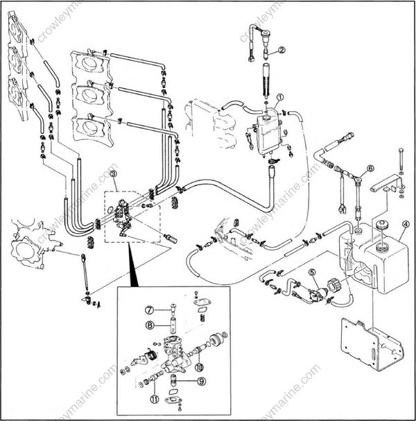
(1) Engine oil tank
(2) Engine oil tank oil level gauge
(3) Oil injection pump
(4) Remote oil tank
(5) Remote oil tank oil feed pump
(6) Remote oil tank oil level gauge
(7) Plunger
(8) Differential plunger
(9) Driven gear
(10) Drive gear
(11) Oil control shaft
REMOVAL
1.Remove
- 1) Referring to the 'EXPLODED DIAGRAM" on page 4-14, remove the oil injection system.
Oil hose
- Inspection
- 1) Inspect each oil hose visually for external damage.
Oil injection pump
- Cleaning
- 1) Referring to the 'EXPLODED DIAGRAM" on page 4-14, disassemble the oil injection pump.
NOTE:
Never disassemble the oil injection pump unless absolutely necessary.
2) Use a petroleum based solvent for cleaning.
Blow out all passages and jets with compressed air.
- Inspection
- 1) Inspect each part visually for damage.
- Assembly
1) Reverse the disassembly procedure.
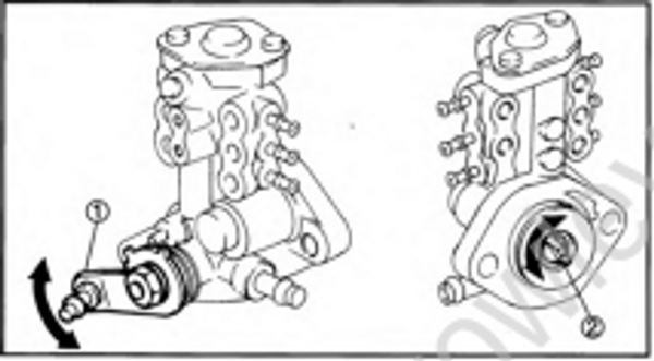
2) Make sure the oil control lever and drive gear rotate smoothly.
(1) Oil control lever
(2) Drive gear
INSTALLATION AND INSPECTION
- Installation.
- 1) Referring to the "EXPLODED DIAGRAM" on page 4-14, install the oil injection pump.
- Bleeding oil line of air and checking operation of oil level warning sytem.
- 1) Referring to page 3-18, bleed the air out of the oil line. At the same time, inspect the oil level warning system (feed pump, oil level indicator lamp and buzzer).
- Inspection.
- 1) Visually inspect each part for oil leakage.