

FUEL JOINT AND FUEL FILTER
EXPLODED DIAGRAM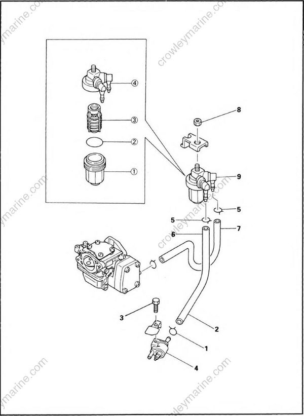
REMOVAL AND INSTALLATION CHART
| Step | Procedure/Part name | Q'ty | Service points |
|---|---|---|---|
| FUEL JOINT AND FUEL FILTER REMOVAL | Follow the left "Step" for removal | ||
| 1 | Clip | 1 | |
| 2 | Fuel hose (joint - filter) | 1 | |
| 3 | Bolt (with washer) | 1 | |
| 4 | Fuel joint | 1 | |
| 5 | Clip | 2 | |
| 6 | Fuel hose (joint - filter) | 1 | |
| 7 | Fuel hose (filter - carburetor) | 1 | |
| 8 | Nut | 1 | |
| 9 | Fuel filter | 1 | |
| FUEL FILTER DISASSEMBLY | |||
| (1) | Filter cup | 1 | |
| (2) | O-ring | 1 | |
| (3) | Filter element | 1 | |
| (4) | Body cover | 1 | |
| Reverse the removal steps for installation |
SERVICE POINTS
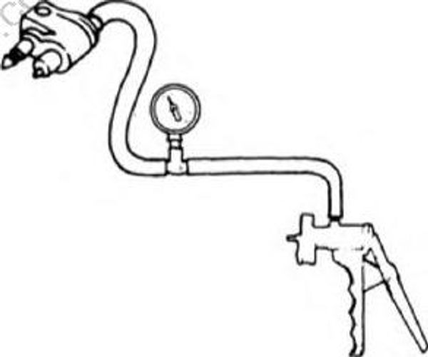
Fuel joint inspection
- Inspect:
- Fuel joint
Crack/Leak/Damage -> Replace.
- Measure:
- Fuel joint operation
Impossible to maintain the specified pres
sure for 10 sec. -> Replace.
Measuring steps:
- Attach the Mity vac.
Mity vac: YB-35956/90890-06756
- Apply the specified pressure.
2 Specified pressure: 50 kPa (0.5 kg/cm2, 7.1 psi)
Fuel filter inspection
- Inspect:
- Filter element
- Filter cup
Crack/Leak/Clog -> Replace.
Contamination -> Clean.