

EXPLODED DIAGRAM
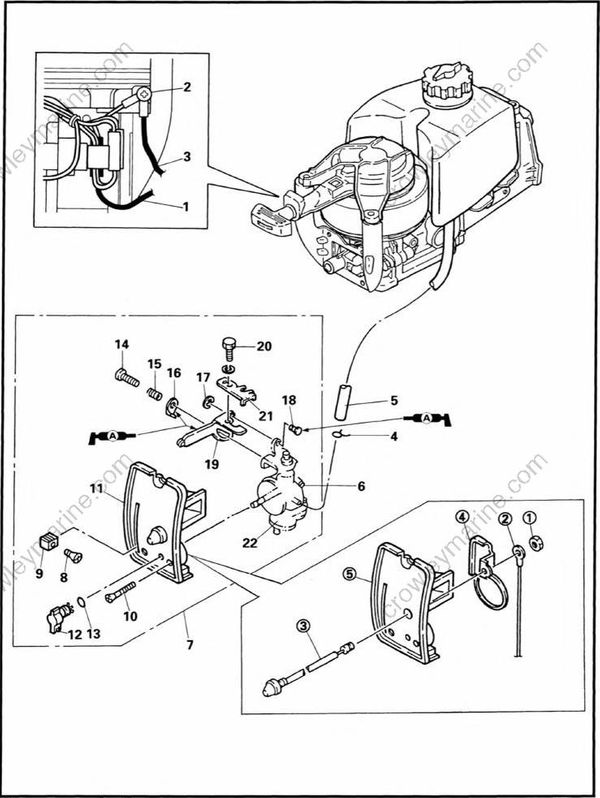
REMOVAL AND INSTALLATION CHART
| Step | Procedure/Part name | Q'ty | Service points |
|---|---|---|---|
| CARBURETOR REMOVAL | Follow the left “Step” for removal. | ||
| Apron | Refer to “FUEL TANK AND FUEL COCK” | ||
| 1 | Stop switch lead (white) | 1 | |
| 2 | Screw | 1 | 5x8 mm |
| 3 | Ground lead (black) | 1 | |
| 4 | Clip | 1 | |
| 5 | Fuel hose (fuel cock - carburetor) | 1 | |
| 6 | Screw | 1 | |
| 7 | Carburetor assembly | 1 | |
| 8 | Screw | 1 | |
| 9 | Throttle lever knob | 1 | |
| 10 | Screw | 2 | 4 x 35 mm |
| 11 | Silencer cover assembly | 1 | |
| 12 | Chock knob | 1 | |
| 13 | O-ring | 1 | |
| 14 | Screw | 1 | 5 x 25 mm |
| 15 | Spring | 1 | |
| 16 | Plate | 1 | |
| 17 | Circlip | 1 | |
| 18 | Pin | 1 | |
| 19 | Accelation arm | 1 | |
| 20 | Bolt (with washer) | 1 | 5x10 mm |
| 21 | Throttle lever link | 1 | |
| 22 | Carburetor assembly | 1 | |
| SILENCER COVER DISASSEMBLY | |||
| (1) | Nut | 1 | |
| (2) | Ground lead | 1 | |
| (3) | Stop switch | 1 | |
| (4) | Bracket | 1 | |
| (5) | Silencer cover | 1 | |
| Reverse the removal steps for installation |