

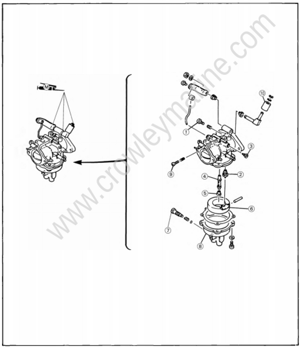
Step 1: EXPLODED DIAGRAM
(1) Pilot screw
(2) Needle valve
(3) Pilot jet
(4) Main nozzle
(5) Main jet
(6) Float
(7) Drain screw
(8) Float chamber
(9) Throttle stop screw
(10) Collar
Step 2: REMOVAL AND DISASSEMBLY
WARNING:
At this step, ensure there is no spillage of gasoline on removing the connections.
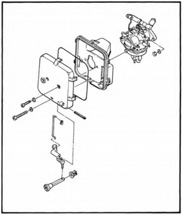
1) Remove the silencer cover, disconnect the fuel hoses and links, then remove the car buretor.
2) Referring to the diagram, use a screwdriver to disassemble the carburetor.
3) Using solvent, clean the components thoroughly, and blow-dry them with com pressed air.
WARNING:
Protect your eyes with suitable safety spectacles or safety goggles when using compressed air. Protect your eyes and the eyes of other persons by directing the flow of compressed-air downward, noting that solvent and small parts may be blown off.
CAUTION:
Do not use steel wire for cleaning the jets as this may enlarge the jet diameters and seriously affect performance.
Step 3: INSPECTION
Carburetor body
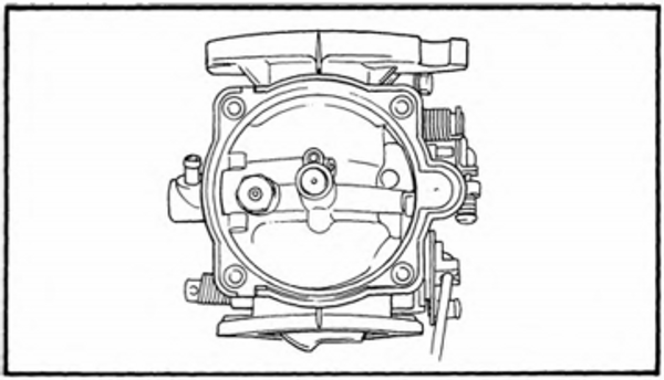
1) Inspect the carburetor body for cracks or clogging of the passages.
Needle valve
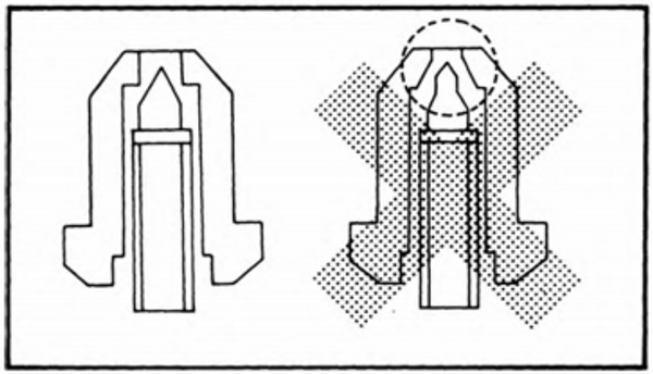
1) Inspect the needle valve for free movement and wear, and replace if required.
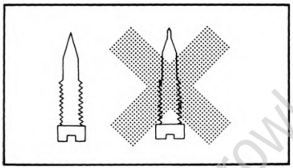
Pilot screw
1) Inspect the needle valve for wear, and replace if required.
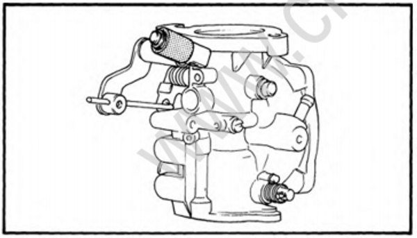
Collar
1) Inspect the collar at the end of the accelerator-arm for wear, and replace if required.
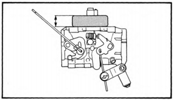
Float
1) Visually inspect the float for damage or cracks, and replace if required.
2) Measure the float height. If it is than the specified float height, recheck the valve seat and needle-valve.
Float height: 18±0.5 mm (0.71 ±0.02 in)
Step 4: ASSEMBLY
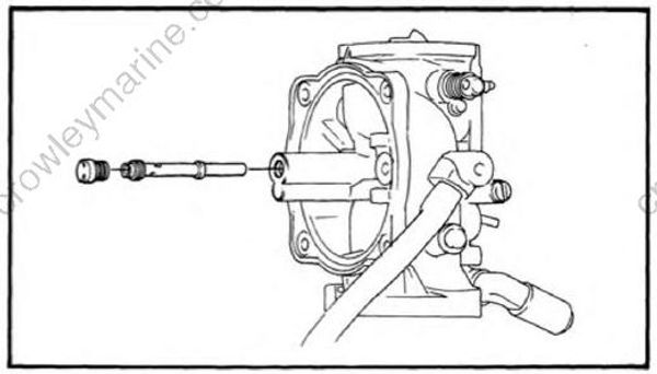
1) Screw in the main nozzle fully, and screw in the main jet until tight.
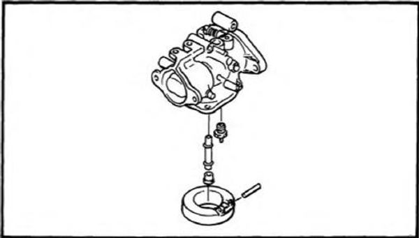
2) Install the needle-valve on the float, attach the float to the carburetor body with the float-pin, and tighten the screw.
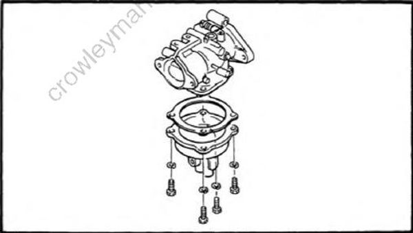
3) Install a new O-ring to the float-chamber, install it to the carburetor body, and secure with the screws.
4) Screw in the pilot jet fully.
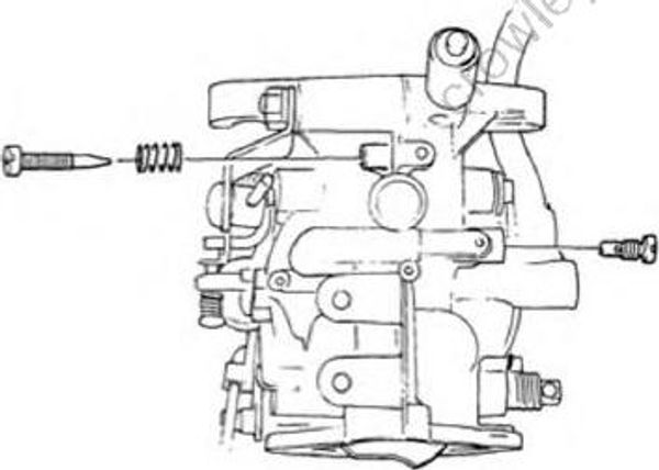
5) Install the pilot-screw with its spring, screw it in until seated then screw it 1 ± 1/2 — 2 turns out.
CAUTION:
Do not cause damage to the tip of the pilot screw by over-tightening it.
Pilot screw, specified turns out:   1 turns plus/minus 1-3/4 ±1/4 turn
Step 5: INSTALLATION
1) Install the carburetors and plate with new gaskets.
2) Connect the fuel hoses to the carburetors, and fit the hose-clips over the recesses to ensure leak-proof connections.
3) Connect the choke link-rods, choke lever and accellerator-lever rod to each
carburetor.
4) Hook the choke-solenoid pull-wire on to the choke arm, and hold it in position with the O-ring.