
CARUBRETION
Description
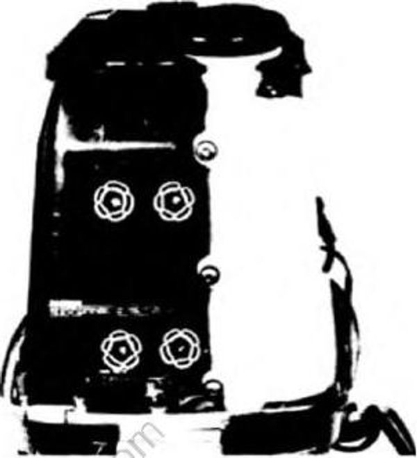
This model is equipped with the triple carburetor of a single barrel type with choke valve.
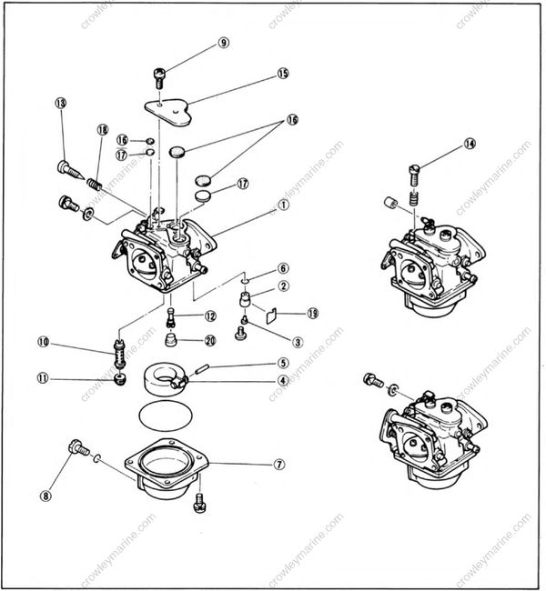
- Mixing chamber
- Valve seat
- Needle valve
- Float
- Hinge pin
- O-ring
- Float chamber
- Drain screw
- Screw
- Main nozzle
- Main jet
- Pilot jet
- Pilot screw
- Throttle adjust screw
- Cover
- Packing
- Plate
- Spring
- Clip
- Cap
Functions of the carburetor
1) Flows of fuel and air (Starting)
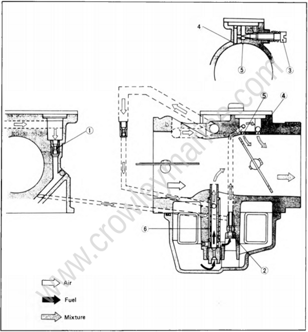
When starting the engine, use the choke, if necessary. By closing the choke valve, a rich mixture is supplied to help the engine start easily.
When the engine is started with the choke valve closed, the air in the carburetor is sucked rapidly into the crankcase, and thus a partial vacuum is produced in the main bore. As a result, fuel is sucked through the main nozzle into the main bore and vaporized by the air streaming in through the hole in the choke valve before entering the crankcase.
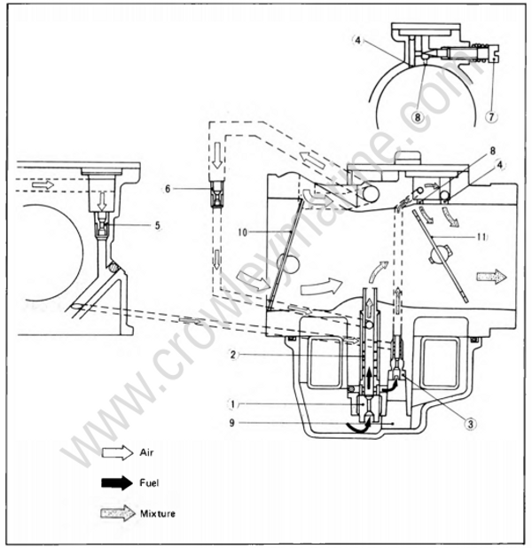
- Main jet
- Main nozzle
- Pilot jet
- Pilot outlet
- Pilot air jet
- Main air jet
- Pilot screw
- Bypass
- Cap
- Choke valve
- Throttle valve
2) Flows of fuel and air (At low speeds)
In the low speed range (idling and trolling), the throttle valve is almost closed. When the crankcase pressure lowers, airfuel mixtures are sprayed into the main bore through the pilot outlet and bypass. The air sucked through the pilot air jet is mixed with the fuel sucked through the pilot jet, and the resultant mixture is metered by the pilot screw and sprayed into the main bore.
When the throttle valve opens and passes the bypass hole (or holes), fuel streams into the main bore. There are three bypass holes, and fuel is sprayed through one or two bypass holes depending on the throttle opening.
NOTE:
The pilot screw meters the flow of fuel at low speeds, and thus stabilizes the engine speed. So it must be set to specification.
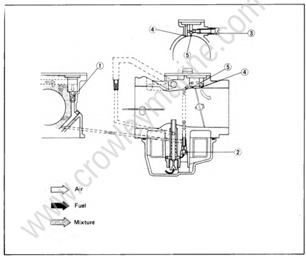
- Pilot air jet
- Pilot jet
- Pilot screw
- Pilot outlet
- Bypass
3) Flows of fuel and air (At medium speeds)
When the throttle valve further opens, mixtures are supplied through the pilot outlet and three bypass holes.
In addition, fuel is supplied little by little through the main nozzle depending on the throttle opening.
- Pilot air jet
- Pilot jet
- Pilot screw
- Pilot outlet
- Bypass
- Main nozzle
- Main air jet
4) Flows of fuel and air (At wide openthrottle)
At wide open throttle, the fuel metered by the main jet is mixed with the air metered by the main air jet in the main nozzle, and the resultant mixture is sucked into the main bore where it is vaporized by air streams. Note that even at open wide throttle, mixtures are supplied through the pilot outlet and bypass holes in the low speed circuit.
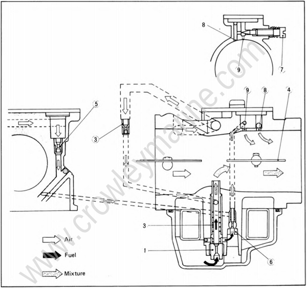
- Main jet
- Main air jet
- Main nozzle
- Throttle valve
- Pilot air jet
- Pilot jet
- Pilot screw
- Pilot outlet
- Bypass
Removal
- Using a slotted-head screwdriver, remove the hose which connects the oil tank to the oil injection pump, from the pump, and immediately insert an M6 bolt into the open end of the hose so that no oil leaks out.
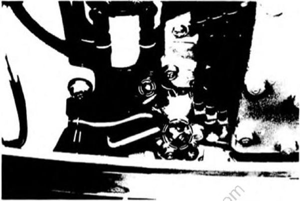
- Remove the oil tank mounting bolt.
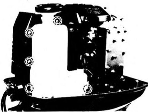
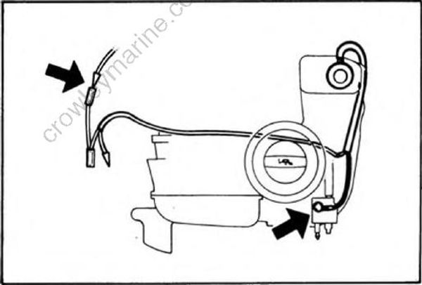
- Disconnect the oil level sensor ground lead and green/red lead, then remove the oil tank from the engine.
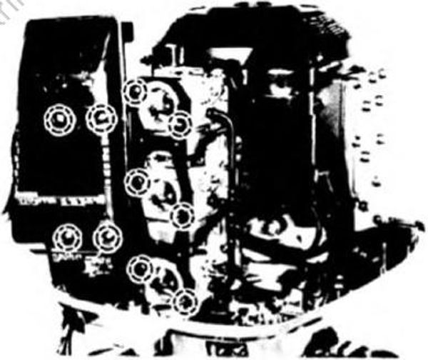
- Remove the silencer cover and stay.
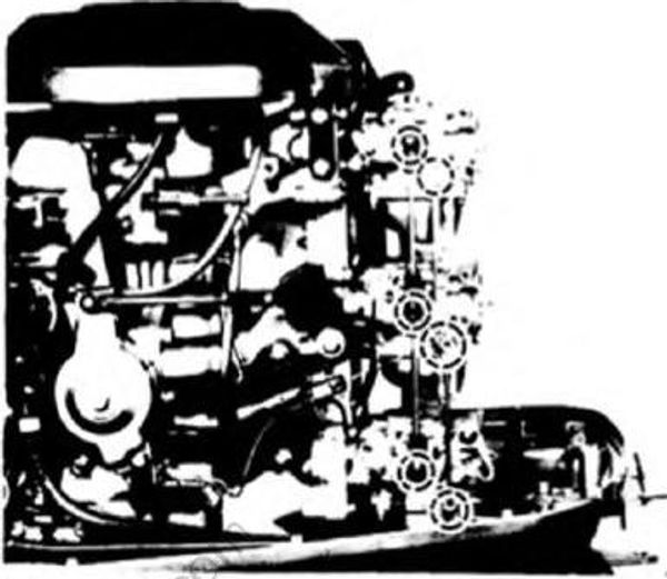
- Disconnect the choke link rod and accelerator lever rod.
- Remove the O-ring from the choke solenoid link.
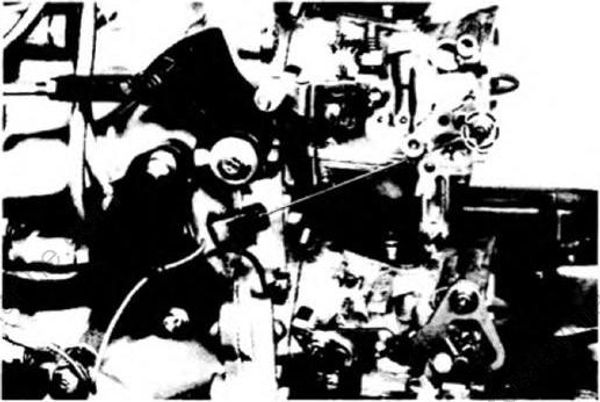
- Disconnect the choke link
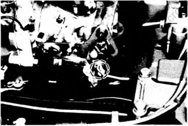
- Disconnect the oil injection pump link rod.
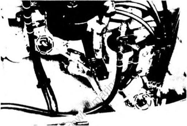
- Remove the clips from the joint of the fuel hose with carburetors, and remove the fuel hose.
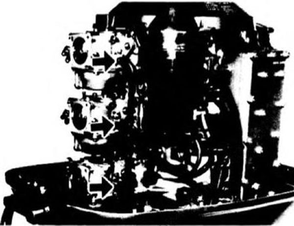
- Remove the carburetor mounting nuts, and remove the carburetor.
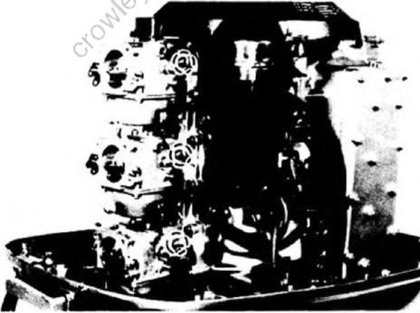
Disassembly
1) Remove the drain screw, and drain off the fuel remaining in the float chamber.
WARNING:
The fuel should be drained into a vessel or dry rags.
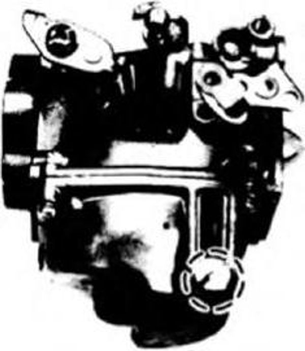
2) Using a slotted-head screwdriver, remove the pilot screw with the spring.
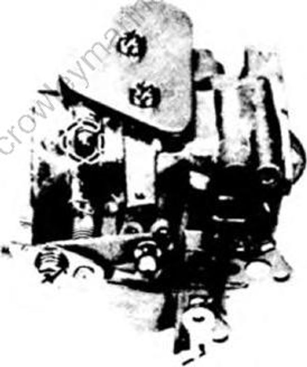
3) Remove the float chamber set screw, and remove the float chamber.
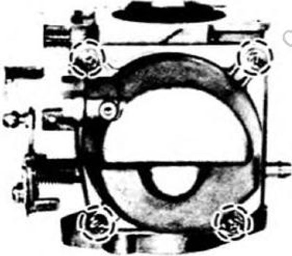
4) Remove the hinge pin set screw, and remove the float with needle valve and hinge pin.
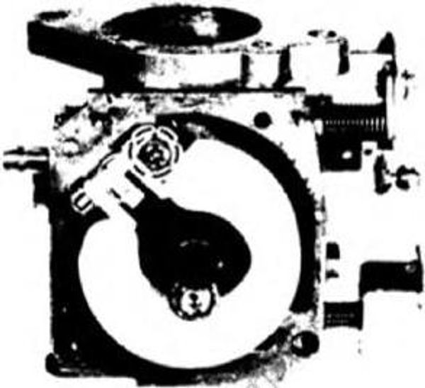
5) Remove the valve seat using a socket wrench.
6) Using a slotted-head screwdriver, remove the main jet and main nozzle.
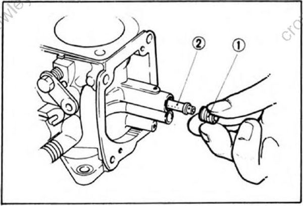
- Main jet
- Main nozzle
7) Remove the cap and using a slotted-head screwdriver, remove the pilQt jet.
8) Remove the screws and remove the cover, packings and plates.
Cleaning, inspection and repair
- Checking fuel and air passages
Check the carburetor body, its parts and the fuel and air passages for fouling or clogging. Clean fouled parts with suitable cleaning solvent, and blow out clogged passages with compressed air.

WARNING:
Be sure to direct compressed air downward as suitable cleaning solvent may get in your eyes or other persons, or small carburetor parts may be blow off.
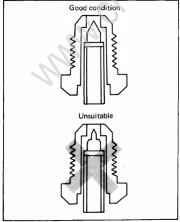
- Checking the needle valve and valve seat
Check the needle valve and valve seat for wear, and if both or either is worn, replace them as a set.
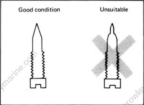
- Checking the pilot screw
Check the pilot screw for wear, and replace it, as required.
- Checking jets and nozzle
Check the air and fuel jets and nozzle for clogging, and clean, if necessary.
Assembly
- Insert the main nozzle until stops, and screw in the main jet until tight.
NOTE:
When screwing in the main nozzle, use care not to damage the threads in the mixing chamber.
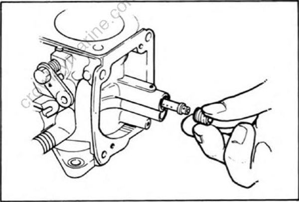
Screw in the pilot jet until stops, and in stall the cap.
Install the O-ring, and screw in the valve seat.
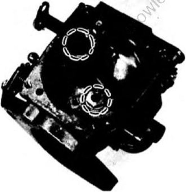
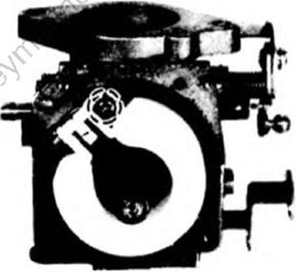
- Install the needle valve on the float, attach the float to the carburetor body with hinge pin and tighten the hinge pin stop screw.
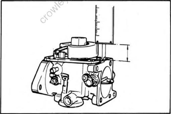
- Measure the float height, if it is 3mm (0.12in) more or less than specified, recheck the valve seat and needle valve.
Float height: 19.5mm (0.77in)
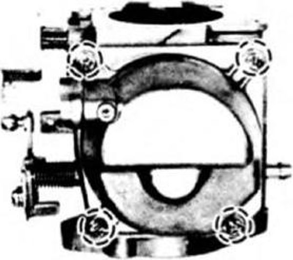
- Hold the float chamber with screws, and screw in the drain screw.
- Install the spring, and screw in the pilot screw until tight. Then back it out as specified.
NOTE:
Never screw in the pilot screw too hard. Stop screwing it in when it is lightly seated.
Turns out of pilot screw: 1-7/8 ± 1/4
- Install the packings, plates and cover, and tighten the screws
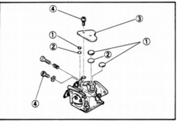
- packing
- Plate
- Cover
- Screw
Installation
- Install the gasket and secure the carburetor to the engine body with nuts and washers.
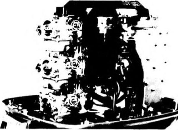
- Install the fuel hose to the carburetor. Fit the clip over the fuel joint recess.
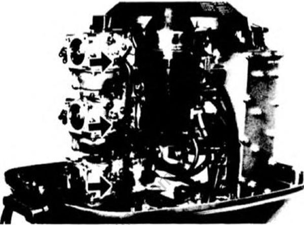
- Connect the choke link to the carburetor choke arm.
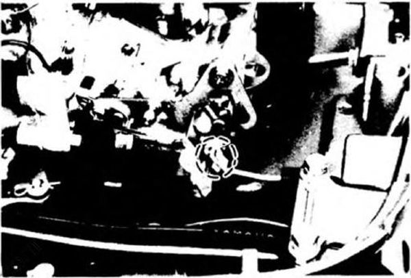
- Hook the choke solenoid pull wire onto the choke arm, and hold it with the 0-ring.
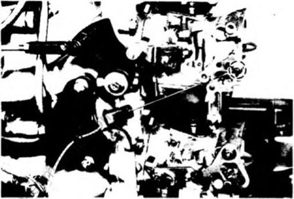
- Install the choke link rod and accelerator lever rod to the carburetors.
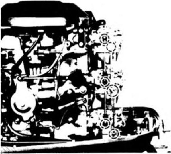
- Connect the oil injection pump link rod to the carburetor and pump.
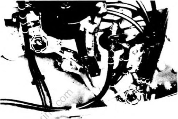
- Install the stay to the carburetors.
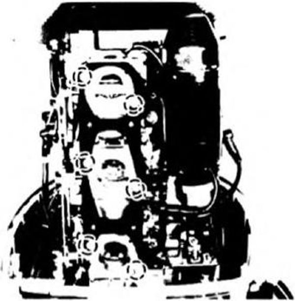
Connect the oil level sensor ground lead and green/red lead.
Install the oil tank onto the engine and secure with the bolts.
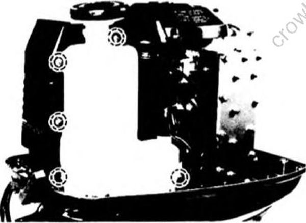
- After installing the oil tank, remove the bolt from the end of the hose, and connect the hose to the oil injection pump, then clip the hose.
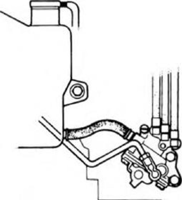
- To bleed the oil injection pump, remove the tank cap, and turn the bleeder screw counterclockwise. After bleeding completely, tighten the screw.
CAUTION:
If no bleeding is made, engine seizure may occur. Whenever the oil tank hose has been removed, be sure to bleed the oil pump.
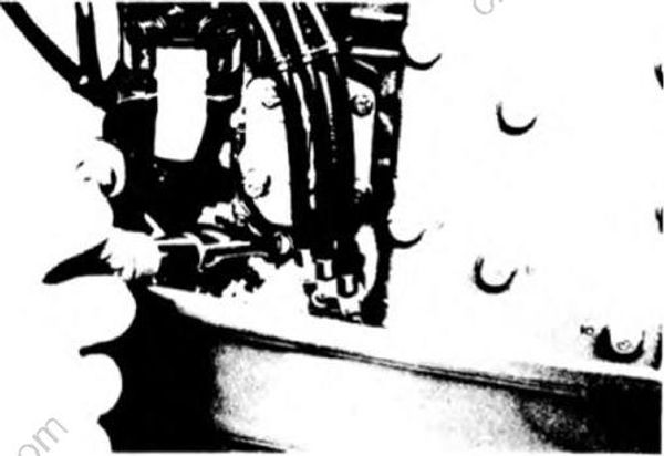
- Install the silencer cover and tighten the screws.
NOTE:
Before installing the silencer cover, make sure the O-rings is attached onto the silencer cover.