

STARTING MOTOR
WARNING:
To avoid dangers of an electric shock, be sure to disconnect the battery wires on the battery before removing the starter motor.
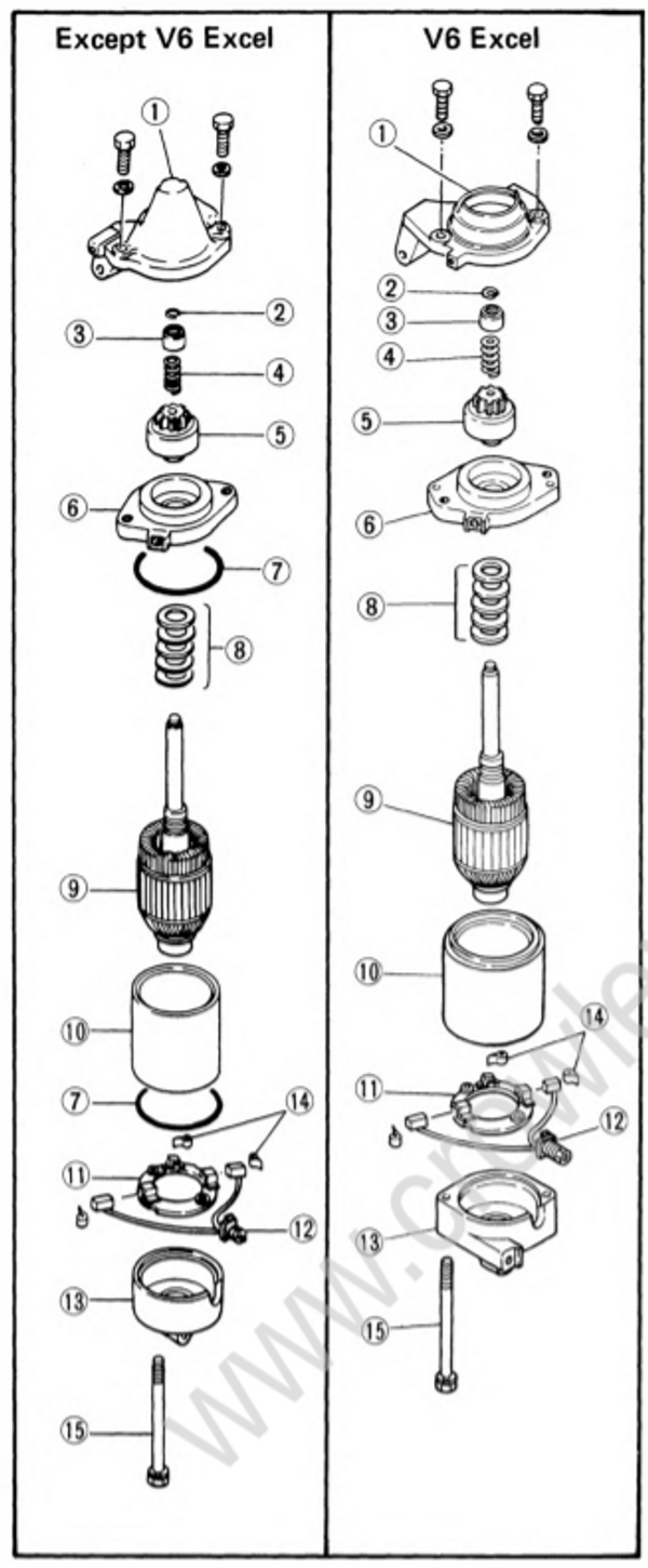
REMOVAL
For removal of starter motor, refer to page 4-18.
DISASSEMBLY
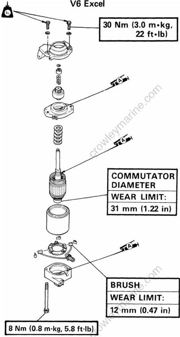
- Remove in sequence:
(1) Pinion cover (from starter motor)
(2) Clip
(3) Pinion stopper
(4) Spring
(5) Pinion (from armature shaft)
Before remove the pinion remove clip, pinion stopper and spring from armature shaft.
NOTE:
Push the pinion stopper by hand toward the pinion, and remove'the clip.
(6) Front cover
(7) O-ring (Except V6 Excel)
(8) Washer
(9) Armature
(10) Stator
(11) Brush holder
(12) Brush
(13) Rear cover
(14) Spring
(15) Through-bolts
INSPECTION
Armature
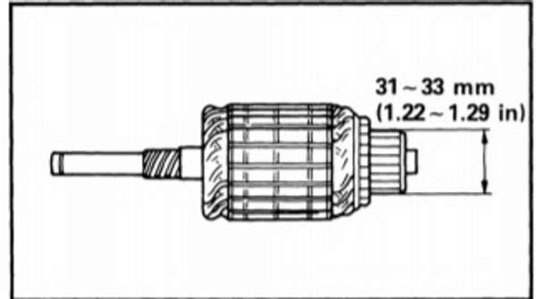
- Inspect:
Commutator (outer surface)
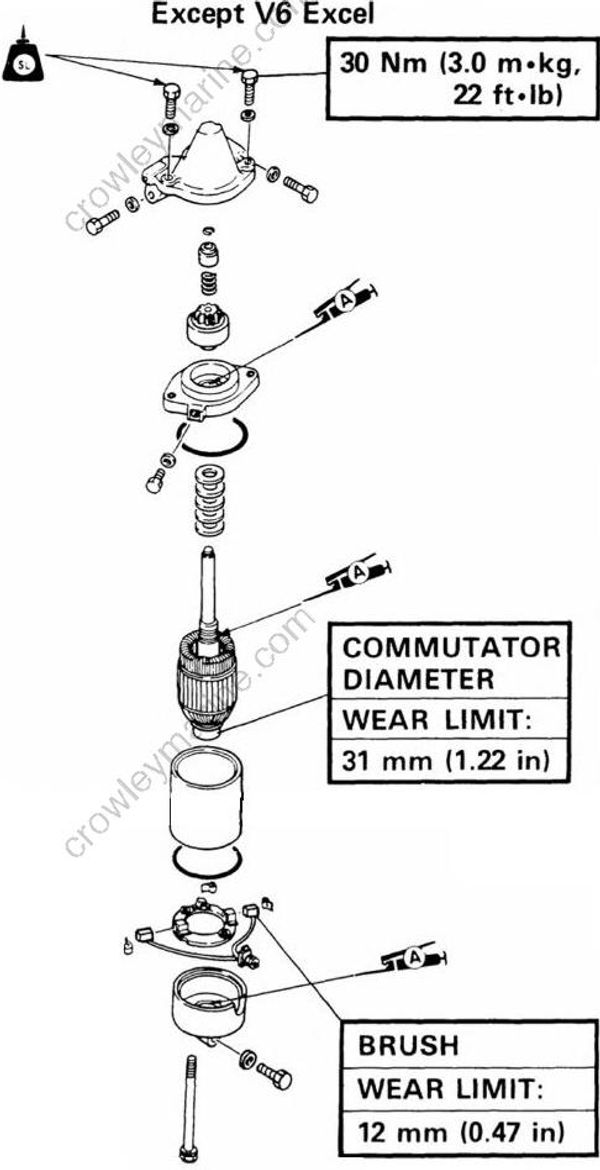
Dirty->Clean with #600 grit sandpaper.Outside dia.
Worn->Replace starter motor.
Minimum outside dia: 31 mm (1.22 in)
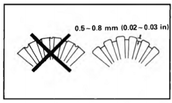
- Mica insulation (between commutator segments)
Over limit->Scrap with appropriately shaped tool (Hacksaw blade can be ground to fit).
Depth of insulator: 0.5 ~ 0.8 mm (0.02 ~ 0.03 in)
Min. allowable undercut depth: 0.2 mm (0.079 in)
NOTE:
The mica insulation of commutator must be under-cut to ensure proper operation of commutator.
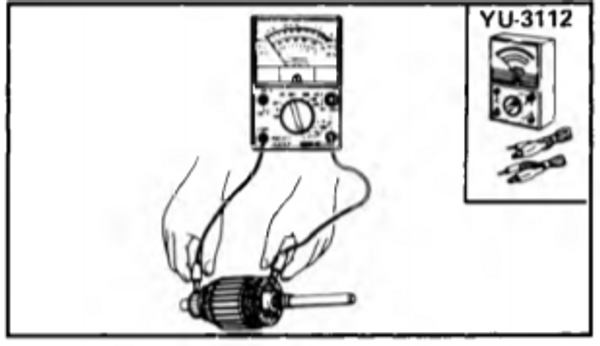
- Measure:
- Armature coil
Continuity (Between armature coil and ground)-> Replace.
Brushes
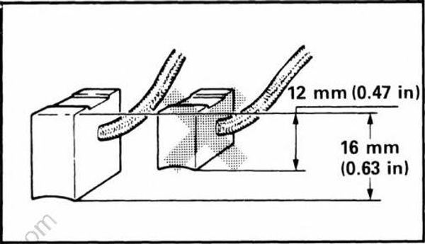
- Measure:
- Brush length (each)
Worn-> Replace.
Minimum brush length: 12 mm (0.47 in)
- Inspect:
- Brush spring pressure
Compare with new spring.
Pressure weaker->Replace spring.
Brush holder
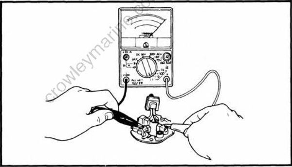
- Inspect:
- Brush holder
Continuity (between brush holder and ground)-> Replace.
Pinion
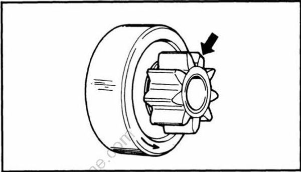
- Inspect:
- Pinion gear
Wear or damage->Replace.
ASSEMBLY
- Install:
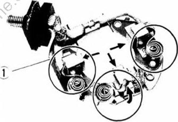
- (1) Brush holder assembly
Push the two brushes apart and insert the commutator between them.
NOTE:
Be careful not to break brushes by forcing the commutator in between the brushes.
- Install:
(1) Brush
(2) Brush spring
(3) Brush holder
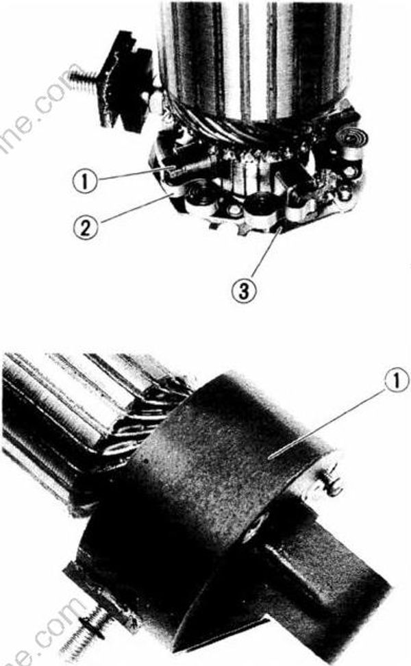
- Install:
- (1) Rear cover
Fit the brush lead terminal to the notch in the rear cover.
NOTE:
- Coat the outer surface of the terminal with a sealant to seal out water.
- Apply a thin film of Marine grease to the bore of the rear cover bushing.
The hole in the rear cover must be aligned with the screw hole in the brush holder.
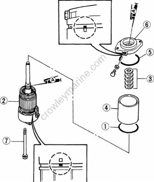
- Install:
(1) O-ring (onto rear cover) (Except V6 Excel)
(2) Armature
NOTE:
Use care not to scratch the brushes when in stalling the armature on the rear cover.
(3) Washer(s)
(4) Stator
Align the cut in the rear cove with the projection on the stator.(5) O-ring (onto stator) (Except V6 Excel)
(6) Front cover
Align the cut in the front cover with the projection on the stator.
NOTE:
Apply a thin coat of Marine grease to the bore of the front cover bushing.
- (7) Through bolts
V6 Excel: 8 Nm (0.8 m-kg, 5.8 ft.lb)
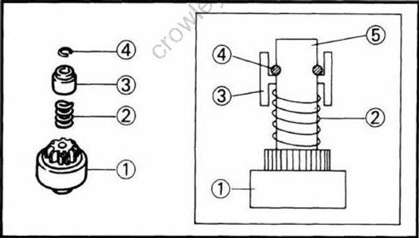
- Install:
(1) Pinion
(2) Spring
(3) Pinion stopper
(4) Clip
Make sure the clip tightly fits in the pinion stopper.(5) Armature shaft
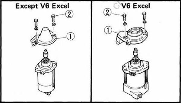
- Install:
(l) Pinion cover
(2) Bolt
INSTALLATION
Refer to Chapter 4.
STARTER RELAY
- Inspect:
- Continuity
No continuity (between the brown and black lead)-> Replace.
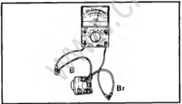
- Operation:
- Connect the tester to relay terminals.
- Connect the 12V battery.
Brown lead-> Positive terminal
Black lead-> Negative terminal
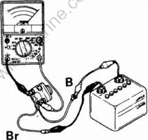
If the relay clicks but the tester needle does not deflector or the relay does not click and the tester needle does not deflect-> Replace.