

IGNITION CONTROL SYSTEM
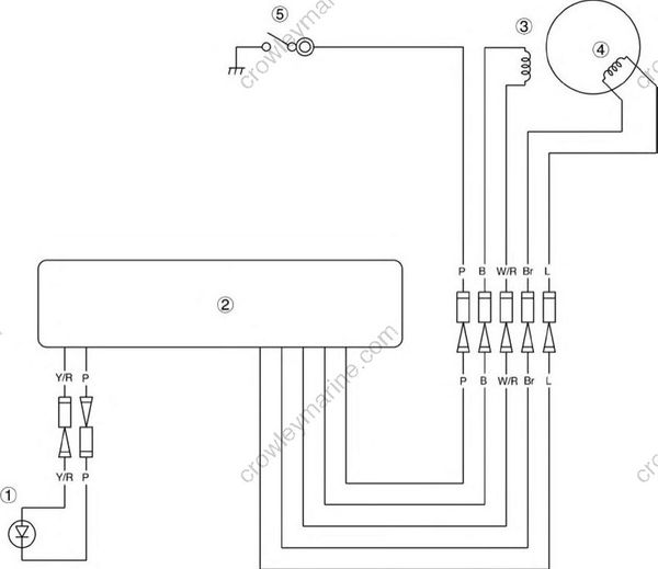
- (1) Emergency signal light
- (2) CDI unit
- (3) Pulser coil
- (4) Charge coil
- (5) Oil pressure switch
Y/R : Yellow/Red
P : Pink
B : Black
W/R : White/Red
Br : Brown
L : Blue
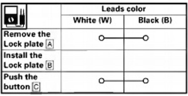
CHECKING THE ENGINE STOP SWITCH
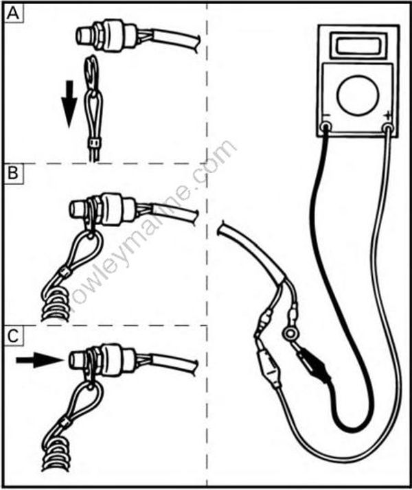
CHECKING THE ENGINE STOP SWITCH
Check:
- Engine stop switch continuity
Out of specification -» Replace.
CHECKING THE PULSER COIL
Check:
- Pulser coil output peak voltage Refer to "CHECKING THE PULSER COIL" on page 8-10.
CHECKING THE OIL PRESSURE SWITCH
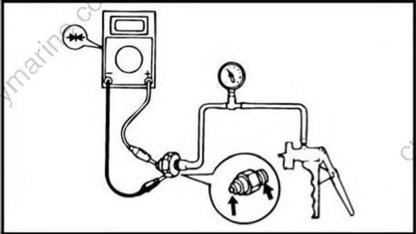
Check:
- Oil pressure switch continuity
Out of specification -> Replace.
| Oil pressure switch continuity pressure: |
|
|---|---|
| 14.7 kPa (0.15 kgf/cm2, 2.13 psi) and above |
No continuity |
| 14.7 kPa (0.15 kgf/cm2, 2.13 psi) and below |
Continuity |
Measuring steps:
(1) Remove the silensor assembly and carburetor.
Refer to "REMOVING/INSTALLING THE INTAKE SYSTEM" on page 4-5
(2) Remove the oil pressure switch.
(3) Connect the mity vac as shown.
Mity vac: YB-35956-A/90890-06756
(4) Slowly operate the mity vac.
(5) Measure the continuity when the specified pressure is reached.
CHECKING EMERGENCY SIGNAL LIGHT
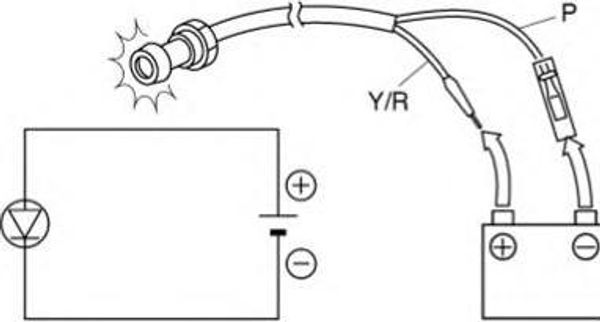
Check:
- Emergency signal light lighting
No lighting -> Replace.
Battery voltage: 12 V
Yellow/Red (Y/R) lead -» Positive terminal.
Pink (P) lead -» Negative terminal.
NOTE:
LED has an direction for electrical current.Therefore try reverse connection if there is no lighting.